Method for energizing a superconducting magnet arrangement

a superconducting magnet and arrangement technology, applied in the manufacture/treatment of superconducting devices, superconducting magnets/coils, magnetic measurements, etc., can solve the problems of reducing the field strength of the magnet arrangement, field inhomogeneities, field instability, etc., to simplify the targeted temperature controlling and simplify the target temperature controlling

Active Publication Date: 2016-02-18
BRUKER SWITZERLAND AG
View PDF32 Cites 4 Cited by
  • Summary
  • Abstract
  • Description
  • Claims
  • Application Information

AI Technical Summary

Benefits of technology

[0027]Screening currents in the tape-like superconductor and the undesirable effects thereof on the strength, homogeneity and stability of the magnetic field are already prevented during cooling and charging of the magnet arrangement, so that subsequent measures for reduction or stabilization of the screening currents can be omitted at least to some extent. As a result the expenditure on both the apparatus and the method is reduced, and technical risks (for example: quenching of the magnet arrangement) are avoided. Moreover an efficient suppression of screening currents proves better and more effective by prevention from the outset than by suppression in retrospect. The most efficient suppression of screening currents may be expected from a combination of the method according to the invention with known methods for subsequent suppression of screening currents. Methods for preventing screening currents already at the time of cooling and charging of a magnet arrangement were known in the past only for pure HTS magnet arrangements. Now owing to the method according to the invention for example they can also be applied to magnet arrangements with windings consisting of high-temperature and low-temperature superconductors (HTS+LTS), which are important in particular for high-field NMR applications.
[0030]Particularly preferred variants of this class of embodiments are characterized in that the temperature-controlling of the superconducting magnet arrangement to a first or a further pre-operating temperature takes place by filling of a container of the cryostat arrangement with liquid nitrogen or by the operation of a cryocooler. Magnet arrangements which are cooled by a liquid gas bath are typically precooled by liquid nitrogen, the boiling temperature of which is below the transition temperature of certain high-temperature superconductors. Thus at this temperature a pre-operating current can already be excited. In the case of cooling by a cryocooler the method according to the invention is particularly advantageous, because the temperature of the magnet arrangement can be adjusted by control of the cryocooler output, which simplifies the targeted temperature-controlling to a pre-operating temperature.
[0031]Particularly preferred variants of this class of embodiments are characterized in that temperature-controlling of the superconducting magnet arrangement to the operating temperature takes place by filling of a container of the cryostat arrangement with liquid helium or by the operation of a cryocooler. Because the cooling procedure of a magnet arrangement cooled by a liquid gas bath by introduction of liquid helium into a container of the cryostat arrangement can take several hours, during this phase pre-operating currents can be excited in the first magnet coil as soon as the temperature of the magnet arrangement has fallen below the first transition temperature. In the case of cooling by a cryocooler the method according to the invention is particularly advantageous, because the temperature of the magnet arrangement can be adjusted by control of the cryocooler output, which simplifies the targeted temperature-controlling to a pre-operating temperature.
[0036]Variants of the method are also preferred in which a first and / or at least one further excited pre-operating current and the first operating current form a chronological sequence of current intensities in the first magnet winding, the values of which decrease towards the end of the sequence, so that in particular the first operating current is smaller than a first excited pre-operating current and / or smaller than at least one further excited pre-operating current. When the current in the first magnet winding decreases to the first operating current, the magnetic field generated by the first magnet winding with its current in the volume of said winding is reduced. Thus for example it is possible to compensate for a field contribution generated by the second magnet winding after excitation of the second operating current in the volume of the first magnet winding.
[0037]Embodiments of the method according to the invention are also especially preferred in which the magnet arrangement is operated after charging in a steady state with constant operating temperature and with constant first and second operating current, in particular as a part of an arrangement for magnetic resonance processes. Such magnet arrangements are cooled and charged only a few times during their life cycle, so that a charging process for preventing permanently flowing screening currents over a particularly long period of time is worthwhile.
[0039]A method according to the invention as described above falls within the scope of the present invention, characterized in that the superconducting magnet arrangement is configured in such a way that the first operating magnetic field at least at one location within the first magnet winding has a component perpendicular to the tape plane which is at least twice as strong as the component perpendicular to the tape plane of the second operating magnetic field at this location. Screening currents are generated in particular by the magnetic field component perpendicular to the tape plane. For example the self-field of a solenoid-like first magnet winding consisting of a high-temperature superconductor tape has a field component perpendicular to the tape plane on the two coil edges. Such coils can be operated within a second magnet winding composed of low-temperature superconductors disposed coaxially around said coils. If the second magnet winding is designed to be substantially longer than the first one in the direction of the common axis, its contribution to the perpendicular field component in the volume of the first magnet winding remains insignificant. The charging method according to the invention is particularly advantageous for such a magnet arrangement, because after running through the sequence of temperature-controlling and pre-operating current excitation stages in the first magnet winding no significant new screening currents can be built up due to the excitation of the second operating current in the second magnet winding. Furthermore, magnet arrangements of this type have the advantage that the wound amount of high-temperature superconductor tape can be minimized, which reduces the production costs.

Problems solved by technology

After charging of such a superconducting magnet arrangement with tape conductors, in particular high-temperature superconductors (=HTS), partially persistent screening currents can flow in the tape which reduce the field strength of the magnet arrangement, or lead to field inhomogeneities and field instability.
After charging of HTS tape conductors partially persistent screening currents flow which reduce the field strength of the magnet arrangement or lead to field inhomogeneity and field instability.
However, until now this method has only been known for pure HTS magnet arrangements.
If a part of the magnet arrangement comprises a low-temperature superconductor, this method could not be used hitherto because with it the charged magnet would be heated above the transition temperature of the low-temperature superconductor, which would inevitably result in “quenching” of the system, that is to say a breakdown of the superconducting currents in the magnet arrangement.

Method used


Image

  • Method for energizing a superconducting magnet arrangement
  • Method for energizing a superconducting magnet arrangement
  • Method for energizing a superconducting magnet arrangement

Examples


Embodiment Construction

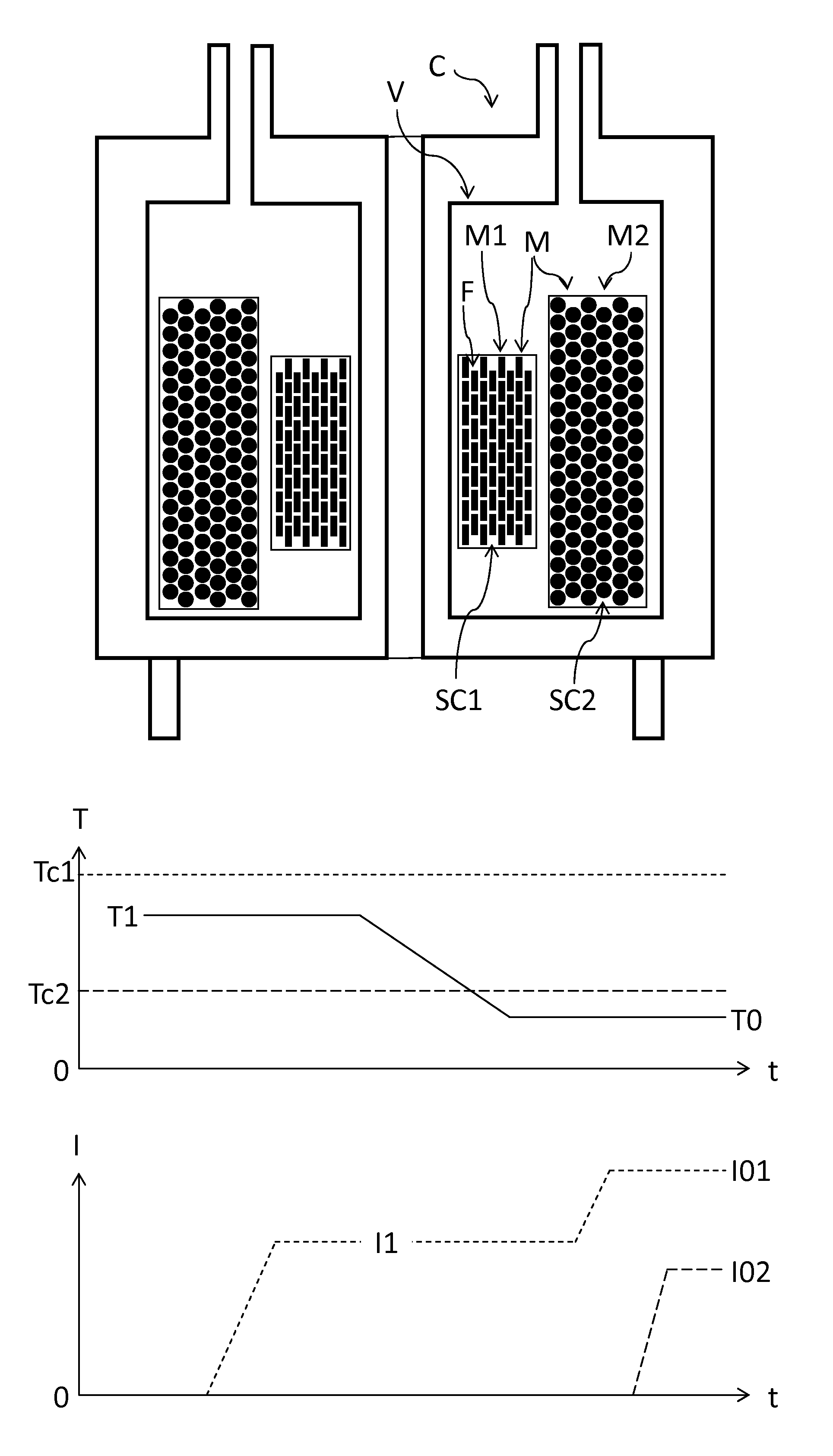
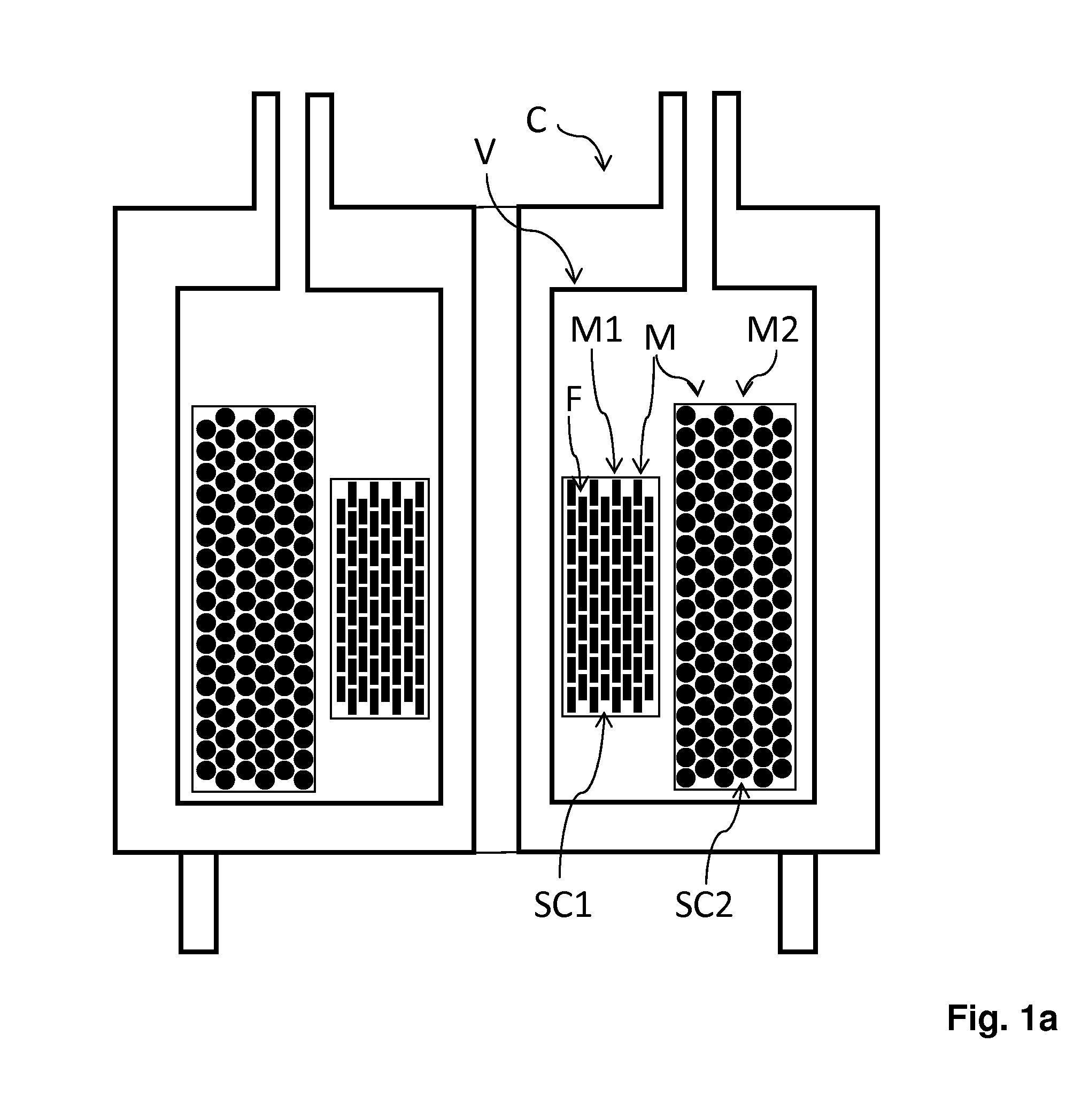
[0061]FIG. 1a shows a schematic sectional representation of a superconducting magnet arrangement M for carrying out the method according to the invention. It comprises a first magnet winding M1 with a tape conductor F composed of a first superconductor material SC1 and a first transition temperature Tc1 and a second magnet winding M2 composed of a second superconductor material SC2 with a second transition temperature Tc2 at least 15 K below the first transition temperature Tc1.

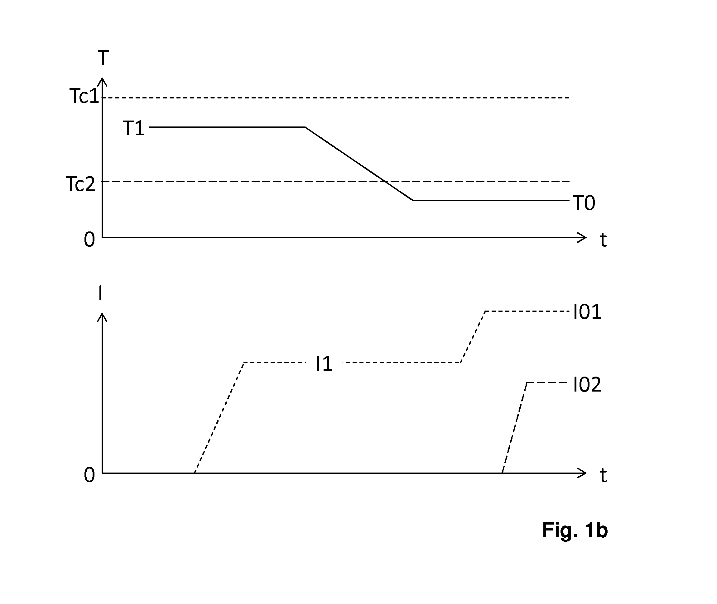
[0062]The magnet arrangement M is disposed in a cryostat device C for cooling to a cryogenic operating temperature T0. The cooling of the magnet arrangement M to the operating temperature T0 or the temperature-controlling of the magnet arrangement M to a pre-operating temperature T1, T2 may take place by filling of a container V with a cryogenic liquid, for example liquid nitrogen or liquid helium.

[0063]As an alternative to this, FIG. 6 shows a cryostat device C with a cryocooler CC for cooling the magnet arr...


PUM

PropertyMeasurementUnit
transition temperatureaaaaaaaaaa
temperatureaaaaaaaaaa

Abstract

A method for charging a magnet arrangement having a superconducting tape conductor with a first transition temperature in a cryostat device. The magnet arrangement is temperature-controlled to a first pre-operating temperature between the first transition temperature and the operating temperature, a first pre-operating current is excited, the magnet arrangement is cooled to operating temperature and a first operating current is excited. The magnet arrangement has a second magnet winding composed of a second superconductor material with a second transition temperature above the operating temperature and at least 15 K below the first transition temperature, wherein a second operating current in the second magnet winding is excited at the latest after cooling of the magnet arrangement to the operating temperature, and with the second operating current the second magnet winding generates a second operating magnetic field in the volume of the first magnet winding.

Description

[0001]This application claims Paris convention priority from DE 10 2014 214 796.4 filed Jul. 28, 2014 the entire disclosure of which is hereby incorporated by reference.BACKGROUND OF THE INVENTION[0002]The invention relates to a method for energizing a superconducting magnet arrangement which is disposed in a cryostat device for cooling to a cryogenic operating temperature and which has a first magnet winding comprising a tape conductor with a first superconductor material and a first transition temperature above the operating temperature, the method comprising the following steps:[0003](a) temperature-controlling of the magnet arrangement to a first pre-operating temperature between the first transition temperature and the operating temperature,[0004](b) excitation of a first pre-operating current after the first pre-operating temperature is reached at least in a part of the first magnet winding,[0005](c) cooling the magnet arrangement to the operating temperature,[0006](b) excitat...

Claims


Application Information

Patent Timeline
Patent Type & Authority Applications(United States)
IPC IPC(8): H01F6/00H01F6/04
CPCH01F6/04H01F6/006G01R33/3815H01F6/02
Inventor SCHAUWECKER, ROBERTVONLANTHEN, PATRIK
Owner BRUKER SWITZERLAND AG
Why Eureka
Try Eureka