Multilayer ceramic capacitor

a multi-layer ceramic and capacitor technology, applied in the direction of fixed capacitors, stacked capacitors, fixed capacitor details, etc., can solve the problems of reducing the reliability of multi-layer ceramic capacitors as a product, reducing the yield in a manufacturing process, and cracks at the boundary between multi-layer units and outer layer sections, so as to reduce or prevent cracks

Active Publication Date: 2016-02-18
MURATA MFG CO LTD
View PDF3 Cites 18 Cited by
  • Summary
  • Abstract
  • Description
  • Claims
  • Application Information

AI Technical Summary

Benefits of technology

[0025]According to various preferred embodiments of the present invention, it is possible to provide a multilayer ceramic capacitor in which it is possible to significantly reduce or prevent the occurrence of cracks caused by an internal stress produced by the difference in the coefficient of thermal shrinkage between a ceramic dielectric layer and a conductive layer, and to provide a multilayer ceramic capacitor array including this multilayer ceramic capacitor and a multilayer ceramic capacitor mount body including this multilayer ceramic capacitor.

Problems solved by technology

The occurrence of cracks reduces the reliability of a multilayer ceramic capacitor as a product or decreases the yield in a manufacturing process.
If the thickness of the above-described other outer layer section is increased or if the thickness of the above-described multilayer unit is increased, cracks occur at the boundary between the multilayer unit and the outer layer section when the body of the multilayer ceramic capacitor is subjected to firing.
Unlike the above-described cracks due to an external stress, this type of crack may occur due to an internal stress produced by the difference in the coefficients of thermal shrinkage between the ceramic dielectric layers and the conductive layers when the body of the multilayer ceramic capacitor is subjected to firing.

Method used


Image

  • Multilayer ceramic capacitor
  • Multilayer ceramic capacitor
  • Multilayer ceramic capacitor

Examples


first preferred embodiment

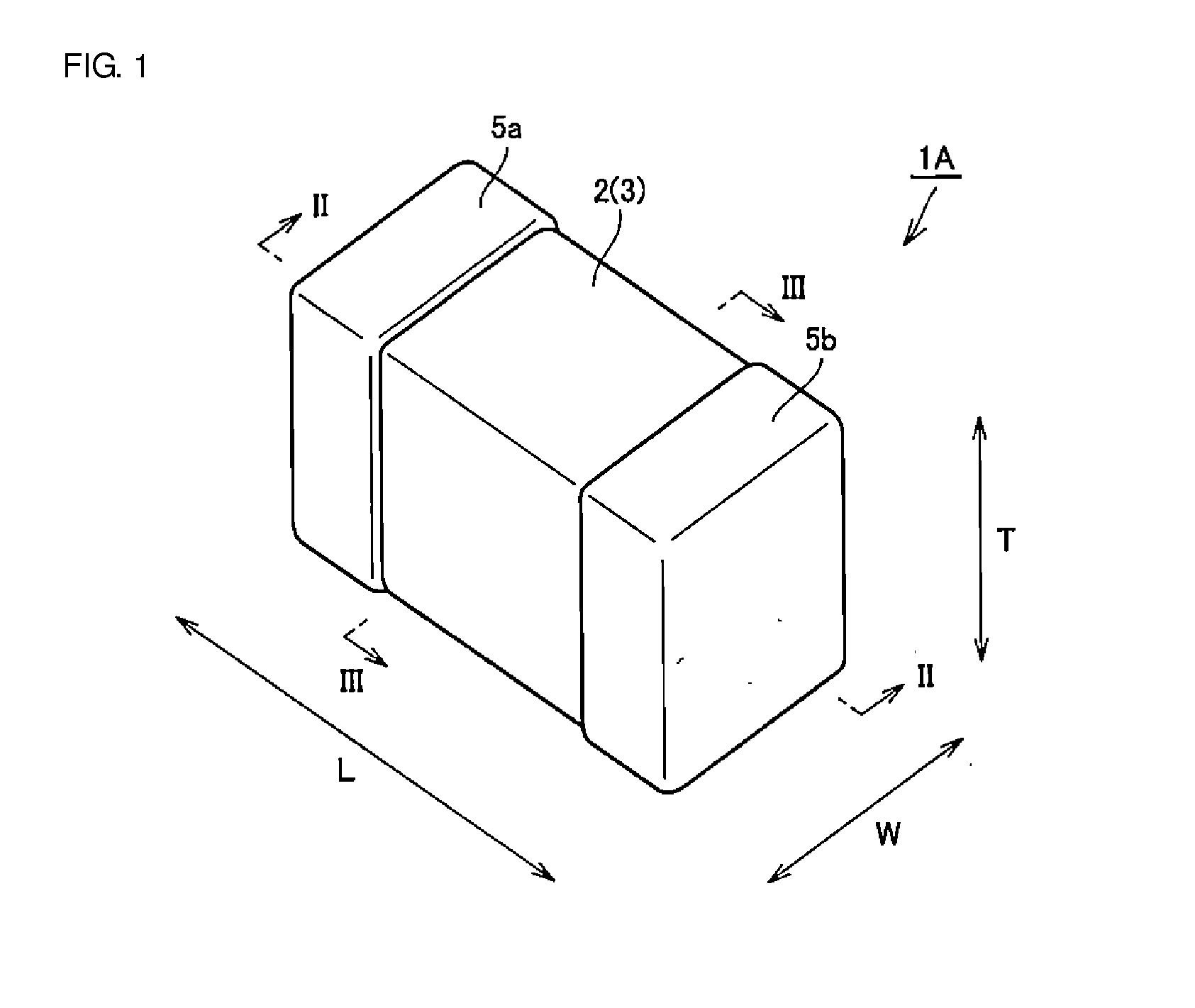
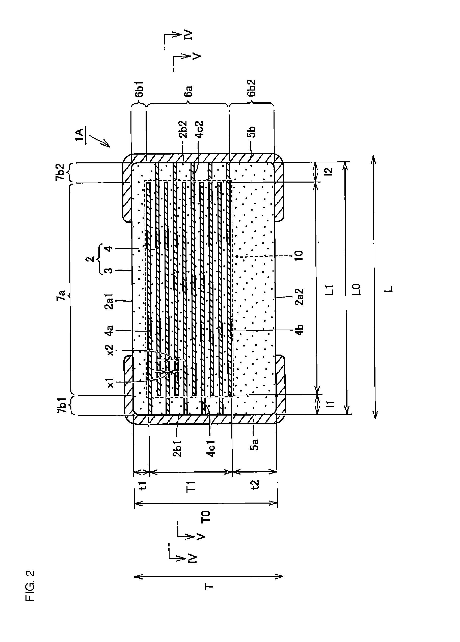
[0047]FIG. 1 is a schematic perspective view illustrating a multilayer ceramic capacitor 1A according to a first preferred embodiment of the present invention. FIGS. 2 and 3 are schematic sectional views taken along lines II-II and III-III, respectively, of FIG. 1. FIGS. 4 and 5 are schematic sectional views taken along lines IV-IV and V-V, respectively, of FIG. 2. The configuration of the multilayer ceramic capacitor 1A of the first preferred embodiment will first be described below with reference to FIGS. 1 through 5.

[0048]As shown in FIGS. 1 through 5, the multilayer ceramic capacitor 1A is an electronic component preferably having a rectangular or substantially rectangular parallelepiped shape and including a body 2 and first and second outer electrodes 5a and 5b, which define a pair of outer electrodes.

[0049]As shown in FIGS. 2 through 5, the body 2 preferably has a rectangular or substantially rectangular parallelepiped shape and includes ceramic dielectric layers 3 and inner ...

second preferred embodiment

[0156]FIG. 13 is a schematic perspective view illustrating a multilayer ceramic capacitor 1B according to a second preferred embodiment of the present invention. FIGS. 14 and 15 are schematic sectional views taken along lines XIV-XIV and XV-XV, respectively, of FIG. 13. The configuration of the multilayer ceramic capacitor 1B of the second preferred embodiment will be described below with reference to FIGS. 13 through 15.

[0157]As shown in FIGS. 13 through 15, the multilayer ceramic capacitor 1B of the second preferred embodiment is different from the multilayer ceramic capacitor 1A of the first preferred embodiment in the configuration of the thickness-direction second outer layer section 6b2, for example. More specifically, the thickness-direction second outer layer section 6b2 of the multilayer ceramic capacitor 1B includes an inner portion 6b21 disposed adjacent to the thickness-direction inner layer section 6a and an outer portion 6b22 which is disposed adjacent to the inner por...

modified example

[0194]FIGS. 16 and 17 are schematic sectional views illustrating a multilayer ceramic capacitor 1C according to a modified example of the second preferred embodiment of the present invention. The cross sections shown in FIGS. 16 and 17 correspond to those shown in FIGS. 14 and 15, respectively. The multilayer ceramic capacitor 1C of this modified example will be described below with reference to FIGS. 16 and 17.

[0195]As shown in FIGS. 16 and 17, the multilayer ceramic capacitor 1C of this modified example is different from the multilayer ceramic capacitor 1B of the second preferred embodiment only in the configuration of the outer portion 6b22 of the thickness-direction second outer layer section 6b2. More specifically, the outer portion 6b22 partially curves and protrudes toward the inner portion 6b21 of the thickness-direction second outer layer section 6b2.

[0196]This will be discussed more specifically. As shown in FIG. 16, a portion of the outer portion 6b22 which corresponds to...


PUM

PropertyMeasurementUnit
thicknessaaaaaaaaaa
thicknessaaaaaaaaaa
thicknessaaaaaaaaaa

Abstract

A multilayer ceramic capacitor includes a multilayer unit, thickness-direction first and second outer layer sections, and width-direction first and second outer layer sections. A dimension of the thickness-direction second outer layer section is greater than a dimension of the thickness-direction first outer layer section. The thickness-direction second outer layer section includes an inner portion and an outer portion. A composition ratio of Si to Ti in a ceramic dielectric layer included in the outer portion is higher than that in the inner portion. A Si content ratio is higher in a boundary portion between the outer portion and the inner portion. A relationship expressed by T1/(W0−W1)≦6.95 is satisfied when a minimum dimension in the width direction of the body is denoted by W0, a minimum dimension in the thickness direction of the multilayer unit is denoted by T1, and a minimum dimension in the width direction of the multilayer unit is denoted by W1.

Description

BACKGROUND OF THE INVENTION[0001]1. Field of the Invention[0002]The present invention relates to a multilayer ceramic capacitor, and a multilayer ceramic capacitor array including a multilayer ceramic capacitor.[0003]2. Description of the Related Art[0004]Generally, a capacitor device includes a body constituted by alternately stacking inner electrode layers and dielectric layers and outer electrodes disposed on the outer surfaces of the body. In a multilayer ceramic capacitor, the dielectric layers are constituted by a ceramic dielectric material.[0005]Generally, the body of a multilayer ceramic capacitor is formed as follows. The body contains a multilayer unit having a substantially rectangular parallelepiped shape and formed by alternately and densely stacking a plurality of conductive layers, which serve as inner electrode layers, and a plurality of ceramic dielectric layers. Outer layer sections constituted by ceramic dielectric layers and outer layer sections constituted by c...

Claims


Application Information

Patent Timeline
Patent Type & Authority Applications(United States)
IPC IPC(8): H01G4/12H01G4/012H01G4/248H01G4/30
CPCH01G4/1218H01G4/012H01G4/248H01G4/30H01G2/06H01G4/1227H01G4/232
Inventor KITANO, SHOTAKATSUYAMA, TAKANOBUSUGITA, HIROAKI
Owner MURATA MFG CO LTD
Why Eureka
Try Eureka