Eddy current braking device for rotary systems

a technology rotary system, which is applied in the direction of braking system, building rescue, transportation and packaging, etc., can solve the problems of system containing a significant amount of rotational inertia, /or the delay of initiation of eddy current braking,

Active Publication Date: 2016-02-25
TRUBLUE
View PDF13 Cites 23 Cited by
  • Summary
  • Abstract
  • Description
  • Claims
  • Application Information

AI Technical Summary

Benefits of technology

[0006]Centrifugal eddy current devices often include multiple biasing elements, one for each deploying rotor. This both increases the complexity of the device and makes bias adjustment more difficult. Indeed, most centrifugal systems are not provided with adjustable biasing which would allow a device to be used in different applications. Rather, centrifugal systems are provided with a manufacturer-selected fixed bias that is determined based on the average load conditions expected for the end-use of the device. In addition, the sheer complexity of the centrifugal design contributes to a high manufacturing cost and a high servicing cost.SUMMARY

Problems solved by technology

Because of the complexity, structure, part count, and mass of incorporating the biasing mechanism(s) into a rotating assembly in which the electrically conductive members deploy centrifugally, the systems contain a significant amount of rotational inertia.
Because of this, the initiation of eddy-current braking can be delayed during deployment, and / or completion of braking can be delayed once the load motion has ceased.
Furthermore, this delay is intrinsic to the design and cannot be controlled or adjusted without redesigning the unit.
Even with such extensive support structure, such devices still require very exacting tolerances to allow the peripherally mounted conductive members to reliably move on the same plane into the magnetic field.
If a conductive member's pivot is out of tolerance even by very slight amounts (something that can occur due to material defect or if a device has been dropped or suffered an impact) the conductive member can make contact with a magnet during braking, thereby damaging the device and preventing correct rotor deployment.
Heat dissipation is also an issue.
Because of this, conductive member heat dissipation (an important factor in eddy current braking) is extremely limited.
Because of the limitations of acceptable device size, a larger retraction spring may not be an option, resulting in a device that cannot handle high cyclic usage (e.g., the retraction spring fatigues and fails rapidly).
This both increases the complexity of the device and makes bias adjustment more difficult.
Indeed, most centrifugal systems are not provided with adjustable biasing which would allow a device to be used in different applications.
In addition, the sheer complexity of the centrifugal design contributes to a high manufacturing cost and a high servicing cost.

Method used


Image

  • Eddy current braking device for rotary systems
  • Eddy current braking device for rotary systems
  • Eddy current braking device for rotary systems

Examples


Embodiment Construction

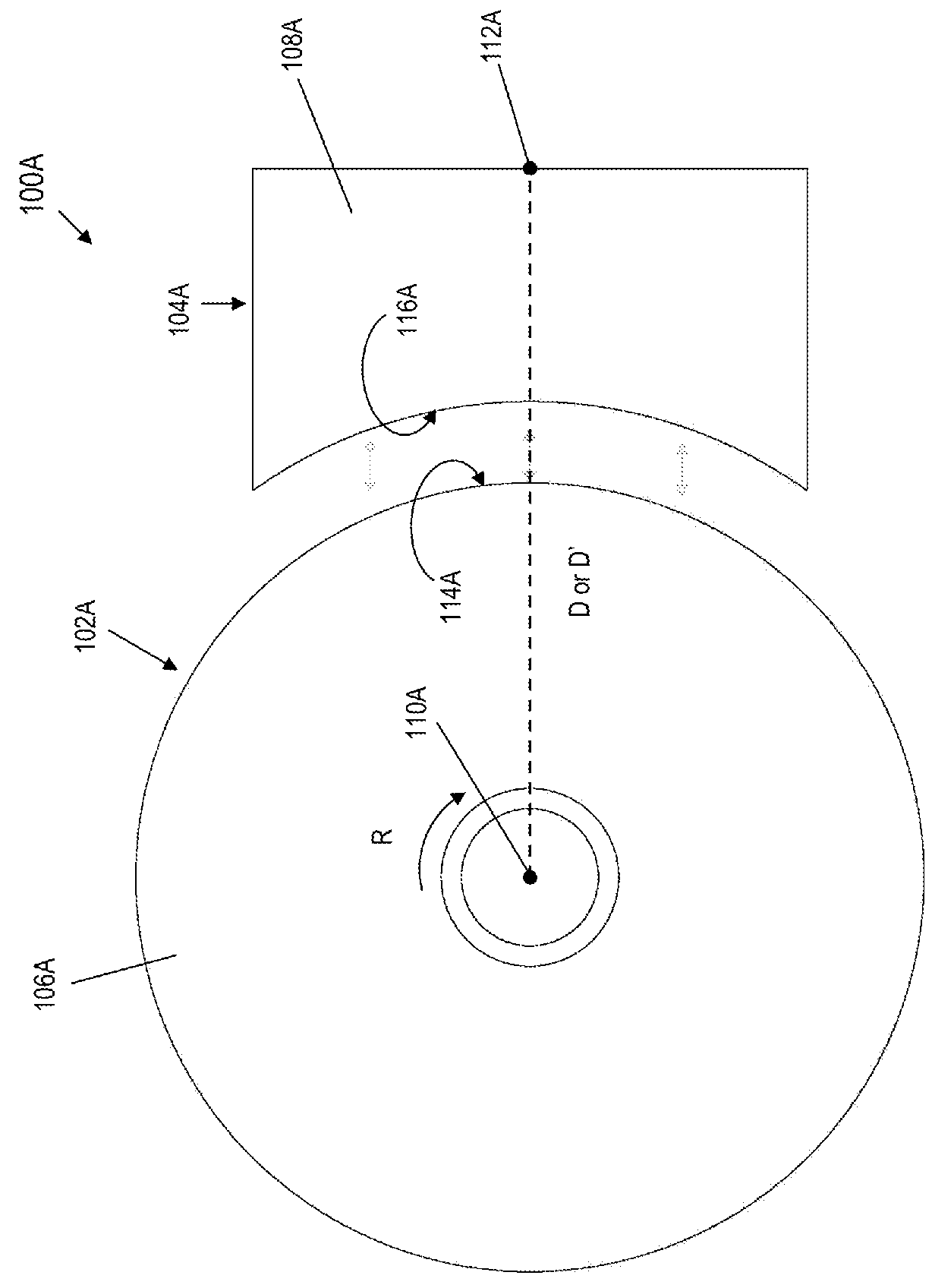
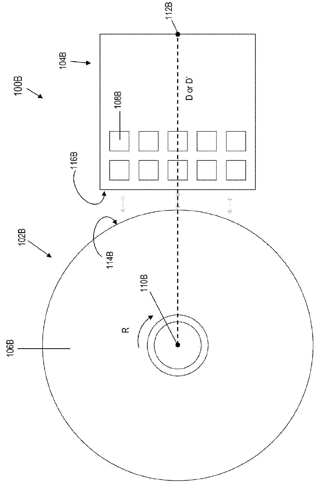
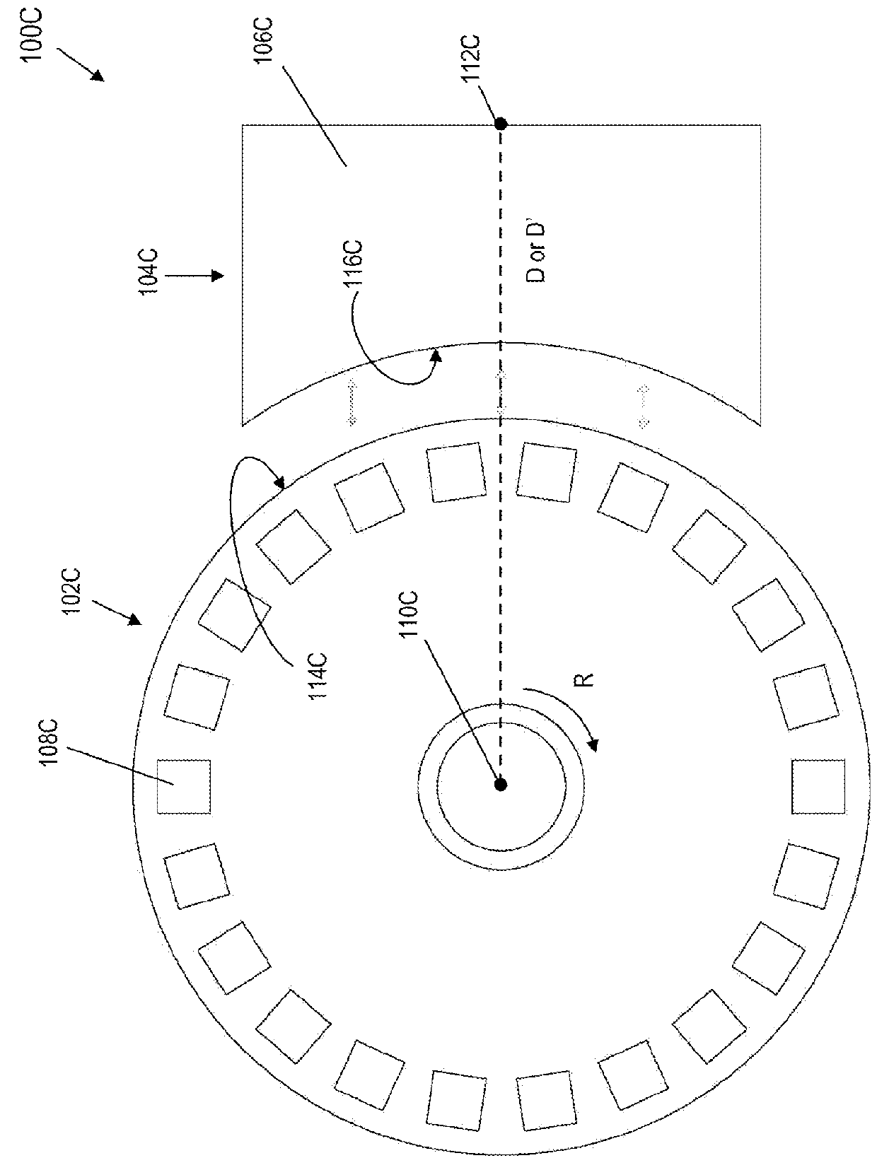
[0026]Several configurations of eddy braking systems are contemplated and depicted in the following figures. FIGS. 1A-1H depict schematic views of first and second portions of eddy current braking systems 100 in accordance with examples of the technology. The various examples are described generally below, with regard to shared aspects, structures, and functions. Components common to systems 100 described in FIGS. 1A-1H are identified only by root numbers (e.g., “first datum 100”), without regard to suffix (e.g., A-H). With regard to specific examples of the eddy current braking systems 100A-H of FIGS. 1A-1H, specifics of the various examples are described following in this general presentation. In general, each braking system 100 includes first portion 102 and a second portion 104. In various examples, each portion 102, 104 can include (or be manufactured from) one or more electrically conductive elements 106 and / or magnetic elements 108. The electrically conductive element is also...


PUM


Abstract

An apparatus has a first portion of a magnetic braking system with a first element disposed thereon. The first portion rotates about an axis. The position of the first element is a fixed distance from the axis. A second portion of the magnetic braking system has a second element disposed thereon. A spring biases the rotatable first portion a first distance from the second portion. Upon application of a force to one of the portions, the relative position of the rotatable first portion to the second portion is reduced to a second distance less than the first distance.

Description

CROSS-REFERENCE TO RELATED APPLICATIONS[0001]This application claims priority to and the benefit of U.S. Provisional Patent Application No. 62 / 039,731, filed Aug. 20, 2014, the disclosure of which is hereby incorporated by reference herein in its entirety.INTRODUCTION[0002]Eddy current braking systems may use centrifugal force to cause rotors to expand into a magnetic field. Centrifugal eddy current devices require significant support structure in the rotating rotor assembly to support the centrifugally deploying electrically conductive members, and to ensure that they remain in plane during deployment so that they don't make contact with magnets. Because of the complexity, structure, part count, and mass of incorporating the biasing mechanism(s) into a rotating assembly in which the electrically conductive members deploy centrifugally, the systems contain a significant amount of rotational inertia. Because of this, the initiation of eddy-current braking can be delayed during deploy...

Claims


Application Information

Patent Timeline
Patent Type & Authority Applications(United States)
IPC IPC(8): B60L7/28
CPCB60L7/28A62B1/08B60T7/128B60T13/748B61H7/083F16D63/002F16D63/008H02K49/046H02K2213/09Y02T10/64B61B3/00
Inventor MCGOWAN, JOHN LEWISHOLMES, STEVEN K.
Owner TRUBLUE
Why Eureka
Try Eureka