
Exhaust valve apparatus and gas filled cushion

a gas-filled cushion and exhaust valve technology, which is applied in the direction of fluid mattresses, umbrellas, synthetic resin layered products, etc., can solve the problems of inability to perform the above procedure, the air cell cushioning material cannot be filled with air and used, and it is difficult for an ordinary user to conveniently use the air cell cushioning material, etc., to achieve convenient use, easy discharge of gas, and easy use again

Inactive Publication Date: 2016-03-03
YOSHIFUSA KATSUTOSHI +3
View PDF7 Cites 30 Cited by
  • Summary
  • Abstract
  • Description
  • Claims
  • Application Information

AI Technical Summary

Benefits of technology

The present invention provides a discharge valve device and a gas cushioning material with a discharge valve part that can easily discharge gas and can be used repeatedly. The gas cushioning material can be filled with gas and discharged as needed, while still maintaining good usability. The gas cushioning material can be easily detached and stored in a smaller space. The gas pressure can be adjusted to provide a comfortable user experience. The discharge valve part is designed to securely close and maintain gas pressure for a long time. A slit is formed between the gas cell rows to separate each gas cell and facilitate bending of the discharge valve part.

Problems solved by technology

In the step in which the user uses the air cell cushioning material, due to the above, if the user injects air into the air cell cushioning material by himself or herself, since there is a need to purchase an air injector on which heat seal equipment is formed and the air injector provided with the heat seal equipment has a relatively large size, it is difficult for an ordinary user to conveniently use an air cell cushioning material.
Consequently, the air cell cushioning material cannot be filled with air and used again.
Therefore, the air cell cushioning material which is fully filled with air will inevitably have a large volume, and as a result, a large space should be required for preserving the air cell cushioning material.
In the case in which the user uses air cell cushioning material again, it is impossible to perform the above procedure.
However, if oil, moisture or a foreign substance is contained in the adhesive layer, coupling of the discharge valve part is insufficient so that it is difficult to use the air cushioning material again.
Even under poor conditions such as a wet condition or a contaminated condition, therefore, filling and discharging of the gas can be performed repeatedly and the gas cushioning material can be used for a long time.

Method used


Image

  • Exhaust valve apparatus and gas filled cushion
  • Exhaust valve apparatus and gas filled cushion
  • Exhaust valve apparatus and gas filled cushion

Examples


first embodiment

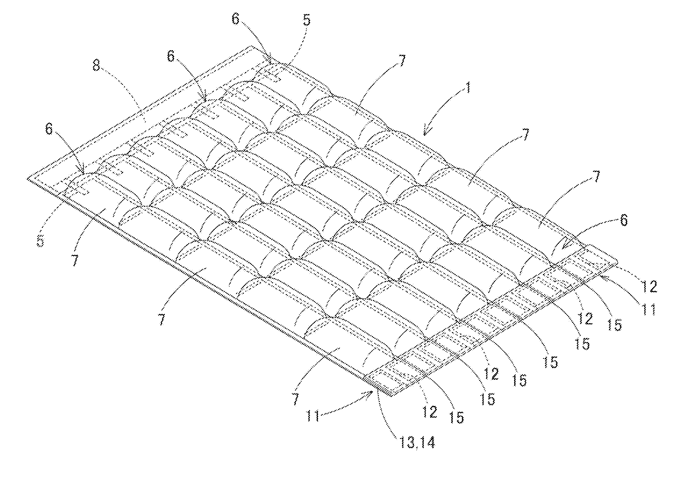
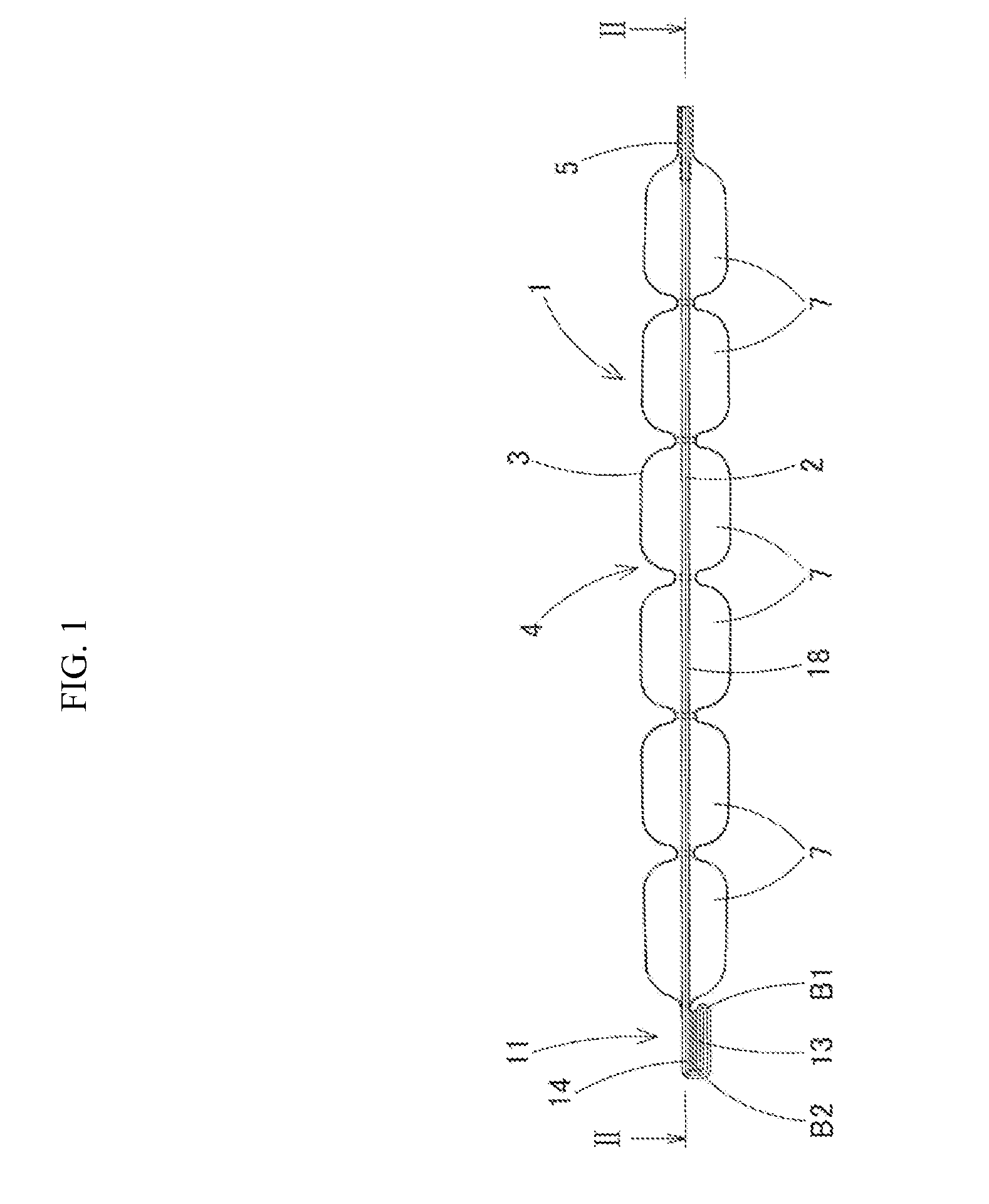
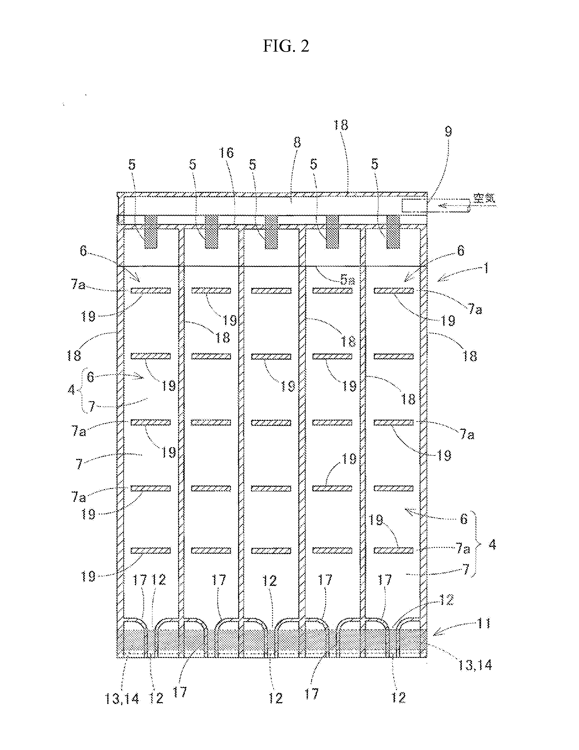
[0051]A gas cushioning material 1 shown in FIG. 1 to FIG. 6 is a gas cushioning material employed as an air mat, an air sitting mat or a gas cell cushioning material for bale-packaging the goods. As shown in FIG. 3, the gas cushioning material 1 is formed in a mat shape by a bag part 4 made of a film, a plurality of gas cell rows 6 are arranged in parallel with the bag part 4, and a plurality of gas cells 7 are disposed side by side on each of the gas cell rows 6 in a longitudinal direction thereof. In addition, a gas introducing passage 8 and a gas injecting check valve 5 are formed at an upper portion of each bag part 4.

[0052]In the gas cushioning material 1, a first film 2 and a second film 3 overlap each other and peripheral portions of the films are heat-fused with a heat-fusion line 18 to form the bag part 4 in a bag shape. And, the gas introducing passage 8 is formed at an upper portion of the gas cushioning material 1 in a transverse direction, and a plurality of the gas ce...

second embodiment

[0101]FIG. 17 to FIG. 21 illustrate a gas cell cushioning material to be used as a gas cushioning material for bottles using the discharge valve device as described above. This gas cell cushioning material for the bottles is mainly utilized as gas cushioning material for the bottles when the bottles are transported. When used, a gas cell 35 is filled with the gas (air, nitrogen, etc.) to use the gas cell cushioning material as a cushioning material. After use, a discharge valve part 61 is opened to discharge the gas and to allow a compact cushioning material to be stored and used again. As shown in FIG. 21, the gas cell cushioning material is employed for packaging a bottle and has a configuration in which the bottle is inserted into a cylindrical cushioning part 50 from an upper opening of a cylindrical cushioning material main body 31, a bottom of the inserted bottle is placed on a bottom cushioning part 51, and a portion including a neck and a head of the bottle protrudes upward...


PUM

PropertyMeasurementUnit
thicknessaaaaaaaaaa
thicknessaaaaaaaaaa
outer circumferenceaaaaaaaaaa

Abstract

A gas cushioning material preserved by easily discharging a gas from a bag part and used by filling the bag part with the gas when used again is provided. Gas cells are disposed in parallel in a gas cell row by forming heat-fusion parts in the transverse direction. A discharge valve part for discharging gas is formed at an end portion of each gas cell row. A narrowed discharge passage is formed in the discharge valve part. When the bag part is filled with a gas, the discharge valve part is bent to close the discharge passage, and in the state in which the discharge valve part is bent, a first surface fastener and a second surface fastener formed on a front surface and a rear surface of the discharge valve part are coupled to each other to maintain a closed state of the discharge passage.

Description

CROSS-REFERENCE TO RELATED APPLICATION[0001]This application claims priority to and the benefit of Japanese Patent Application No. 2014-177527, filed on Sep. 1, 2014, the disclosure of which is incorporated herein by reference in its entirety.BACKGROUND[0002]1. Field of the Invention[0003]The present invention relates to a discharge valve device having a structure in which a discharge valve part is formed at one end of a bag part made of a film for discharging a gas with which the bag part is filled, the discharge valve part is bent to block a flow of the gas and the discharge valve part is opened to discharge the gas, and relates to a gas cushioning material which is used as a gas cell type cushioning material utilizing the above discharge valve part for an air mat, an air sitting mat, an air pillow and a bale-package material and which can be used as a sleeping bag, an article against the cold, a simplified tent, a simplified awning, and which can be preserved by easily dischargin...

Claims


Application Information

Patent Timeline
Patent Type & Authority Applications(United States)
IPC IPC(8): A47G9/10A47C27/08A47C27/10A47G9/08F16K24/04F16K31/44
CPCA47G9/1027F16K24/04A47C27/10A47G9/08A47C27/081F16K31/44B65D81/03B65D81/052B32B27/08B32B27/32B32B27/34B32B3/02B32B3/08B32B3/28B32B2250/02B32B2250/04B32B2250/24B32B2255/10B32B2255/205B32B2307/304B32B2307/31B32B2307/412B32B2307/7242B32B2419/00B32B2471/04B32B2601/00B32B7/05B32B15/00
Inventor YOSHIFUSA, KATSUTOSHIYOSHIFUSA, HIROTAKAPARK, LEE-JIN
Owner YOSHIFUSA KATSUTOSHI
Learn More