
Computer system, computer, and load balancing method

a load balancing and computer technology, applied in the computer field, can solve the problems of increasing the number of application servers to be increased, affecting the processing efficiency of the system, and not determining whether the processing can be conducted in consideration, so as to achieve the effect of simple configuration

Active Publication Date: 2016-03-03
HITACHI LTD
View PDF6 Cites 12 Cited by
  • Summary
  • Abstract
  • Description
  • Claims
  • Application Information

AI Technical Summary

Benefits of technology

This patent text describes a way to distribute loads on computers to avoid overloading certain components, such as application servers or name servers. The invention allows for a simpler and less expensive way to manage increases in processing requests and external systems. The technical effect of this invention is to improve the scalability and reliability of computer systems without increasing management costs.

Problems solved by technology

Normally, the number of application servers is increased along with an increase in the number of external systems or an increase in a processing request amount, but the load balancing apparatus or the name server becomes a bottleneck, and hence the number of the application servers to be increased reaches a limit.
Further, by placing the load balancing apparatus or the name server, apparatus to be managed within a system increase in number, which increases a management cost.
However, it is not determined whether the processing can be conducted in consideration of situations of other servers.
However, with information on the entire server and information on each server, it is difficult to predict the load status to be imposed on each server in the future, which cannot improve efficiency of the load balancing.

Method used


Image

  • Computer system, computer, and load balancing method
  • Computer system, computer, and load balancing method
  • Computer system, computer, and load balancing method

Examples


Embodiment Construction

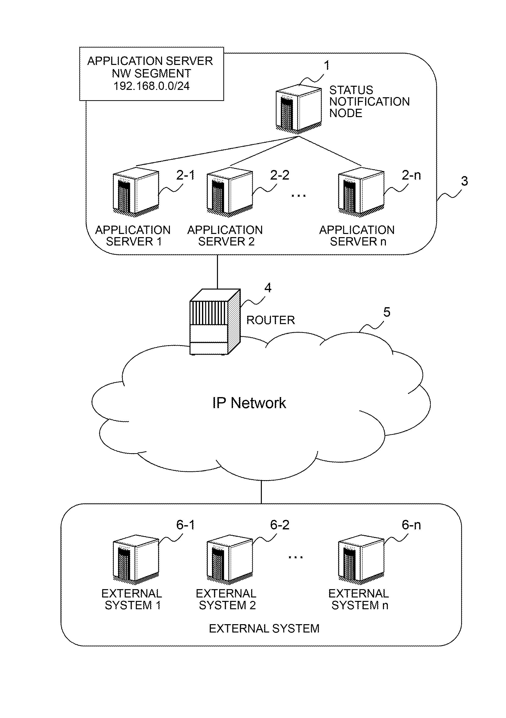
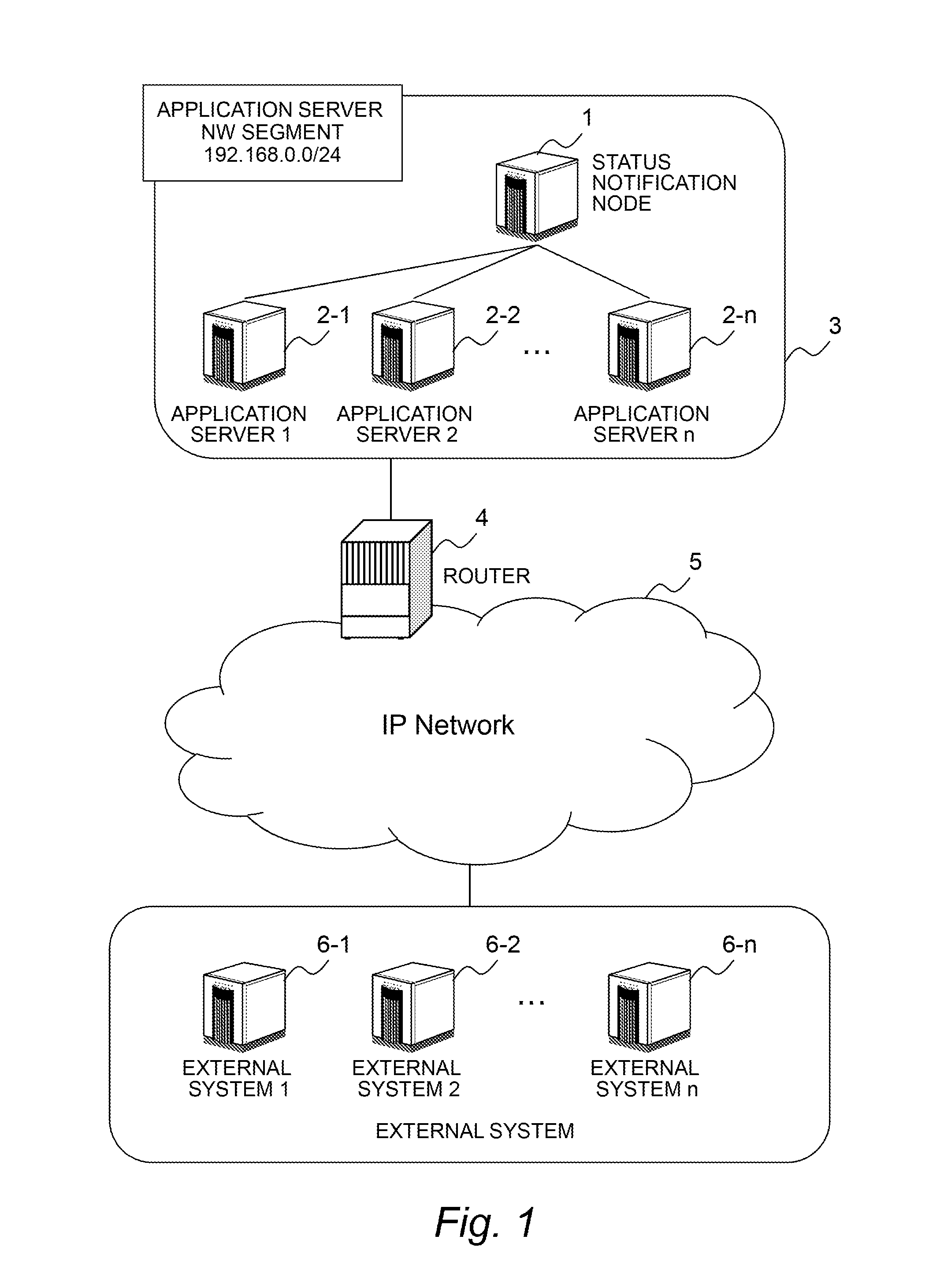
[0046]FIG. 1 is a diagram illustrating an outline of a network for coupling between an application server 2 and an external system 6 for accessing the application server 2 according to a first embodiment of the invention.

[0047]First, with reference to FIG. 1, a description is made of an outline of a network for terminal-server communications in regard to the application server 2 (distributed node) according to this embodiment and the outline of the network between the application server 2 and the node. An application server 2-1 to an application server n (2-n) have IP addresses within the same network segment, and are coupled to one another within one segment under a router 4. Further, a status notification node 1 is provided within the network segment containing the application servers 2-1 to 2-n. A plurality of external systems 6-1 to 6-n transmit a processing request to each of the application servers 2-1 to 2-n via a network 5 and the router 4.

[0048]The network 5 may be an IP ne...


PUM


Abstract

It is provided a computer system, comprising a plurality of computers configured to execute processing in response to requests received from a plurality of external systems. The plurality of computers each share an acceptance weight statistic value calculated by each of the plurality of computers with another computer within the same network segment. The processor of each of the plurality of computers is configured to: receive a broadcast transmitted from one of the plurality of external systems to the same network segment; determine whether to respond to the received broadcast by referring to the shared acceptance weight statistic value; and send a response to the one of the plurality of external systems that has transmitted the broadcast in order to allow the one of the plurality of external systems to transmit a processing request in a case where it is determined to respond to the received broadcast.

Description

CLAIM OF PRIORITY[0001]The present application claims priority from Japanese patent application JP 2014-178100 filed on Sep. 2, 2014, the content of which is hereby incorporated by reference into this application.BACKGROUND OF THE INVENTION[0002]This invention relates to a computer, and more particularly, to a computer for executing an application.[0003]<Architecture of Distributed Application Infrastructure>[0004]In recent years, some distributed application servers have a fixed architecture exhibiting high reliability, which provides an alternate server by ACT-STANDBY in advance, in order to facilitate scaling out of server nodes and ensure redundancy. In addition, there is proposed an architecture in which nodes that are arranged in a distributed manner are monitored, a status notification node notifies other nodes of a status of each node, and the respective nodes grasp the status of each other, thus taking over a node in which a failure has occurred.[0005]In JP 2006-33862...

Claims


Application Information

Patent Timeline
IPC IPC(8): H04L45/16
CPCH04L67/1023H04L67/101H04L67/1008H04L67/1029
Inventor MIYATA, TATSUHIKOYOSHIHARA, JUN
Owner HITACHI LTD
Learn More