Wheel for pedal-assisted bikes

a technology for pedal-assisted bikes and wheels, which is applied in the direction of bicycles, cycles, transportation and packaging, etc., can solve the problems of delayed transmission, inability to achieve the end user, and inability of the first plate to immediately grip the second pla

Active Publication Date: 2016-03-10
C R D CENT RICERCHE DUCATI TRENTO
View PDF7 Cites 21 Cited by
  • Summary
  • Abstract
  • Description
  • Claims
  • Application Information

AI Technical Summary

Problems solved by technology

Furthermore it should be emphasized that the application of a kit for pedal-assisted bikes in a post-sales stage, even if possible, usually needs to perform inconvenient and impractical operations for adjusting and fixing the various components to the frame, which most of the times can not be accomplished by the end user and require the intervention of an expert technician.
Under higher load conditions (e.g. pedaling uphill), on the contrary, the first plate is not able to immediately grip the second plate.
The wheel shown in WO 2012 / 123802, however, is susceptible of upgrading aimed at improving the user's driving comfort and the system's efficiency.
During the thrust phase of pedaling, in fact, the presence of grip ramps delays the transmission of torque from the pedal crank to the wheel.
Under both conditions, this behavior of the wheel is felt by the user as annoying and as an obstacle to pedaling.

Method used


Image

  • Wheel for pedal-assisted bikes
  • Wheel for pedal-assisted bikes
  • Wheel for pedal-assisted bikes

Examples


Embodiment Construction

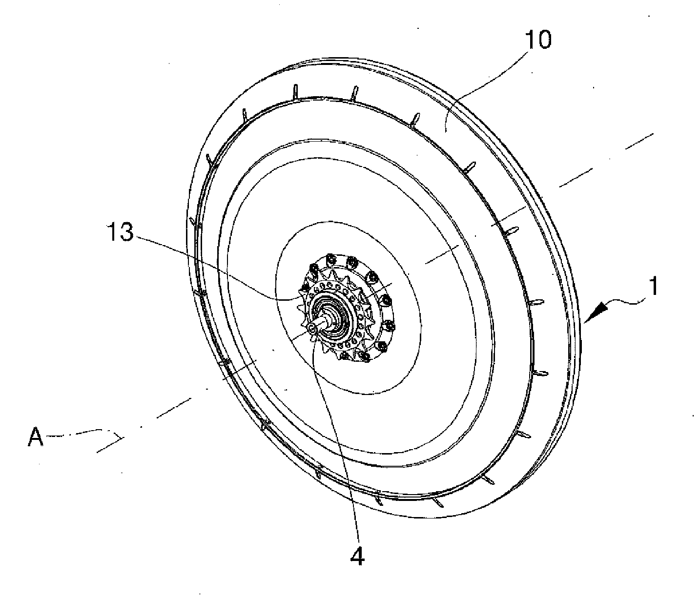
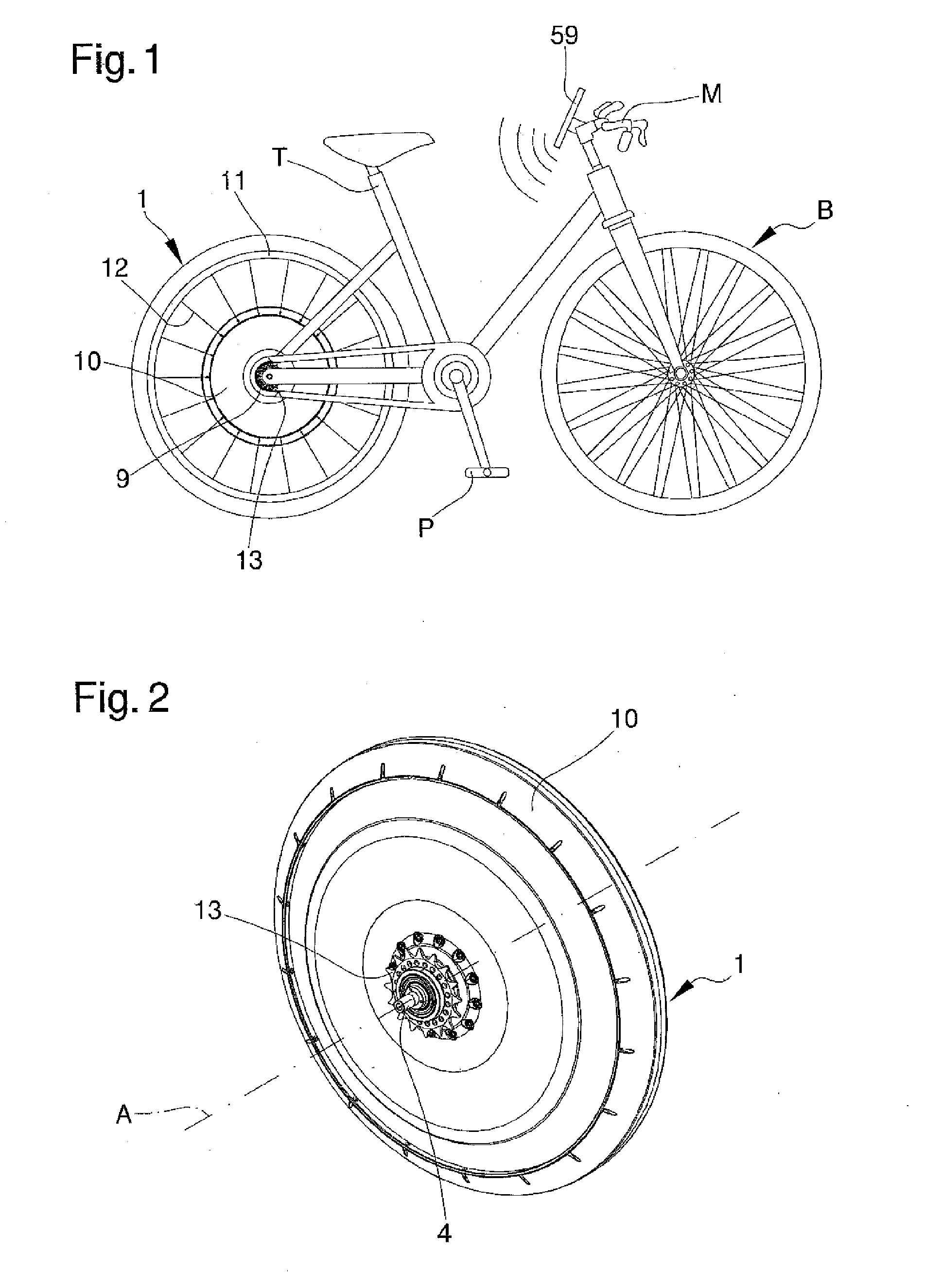
[0030]The main aim of the present invention is to provide a wheel for pedal-assisted bikes that may be mounted on any traditional model of already existing bike providing it in a practical, easy and functional way with the functions of pedal-assisted bikes and which, at the same time, has a better driving comfort and is more efficient.

[0031]Another object of the present invention is to provide a wheel for pedal-assisted bikes which may overcome the above mentioned drawbacks of the prior art in the ambit of a simple, rational, easy and effective to use as well as low cost solution.

[0032]The aims described above are achieved by the present wheel for pedal-assisted bikes according to claim 1.

BRIEF DESCRIPTION OF THE DRAWINGS

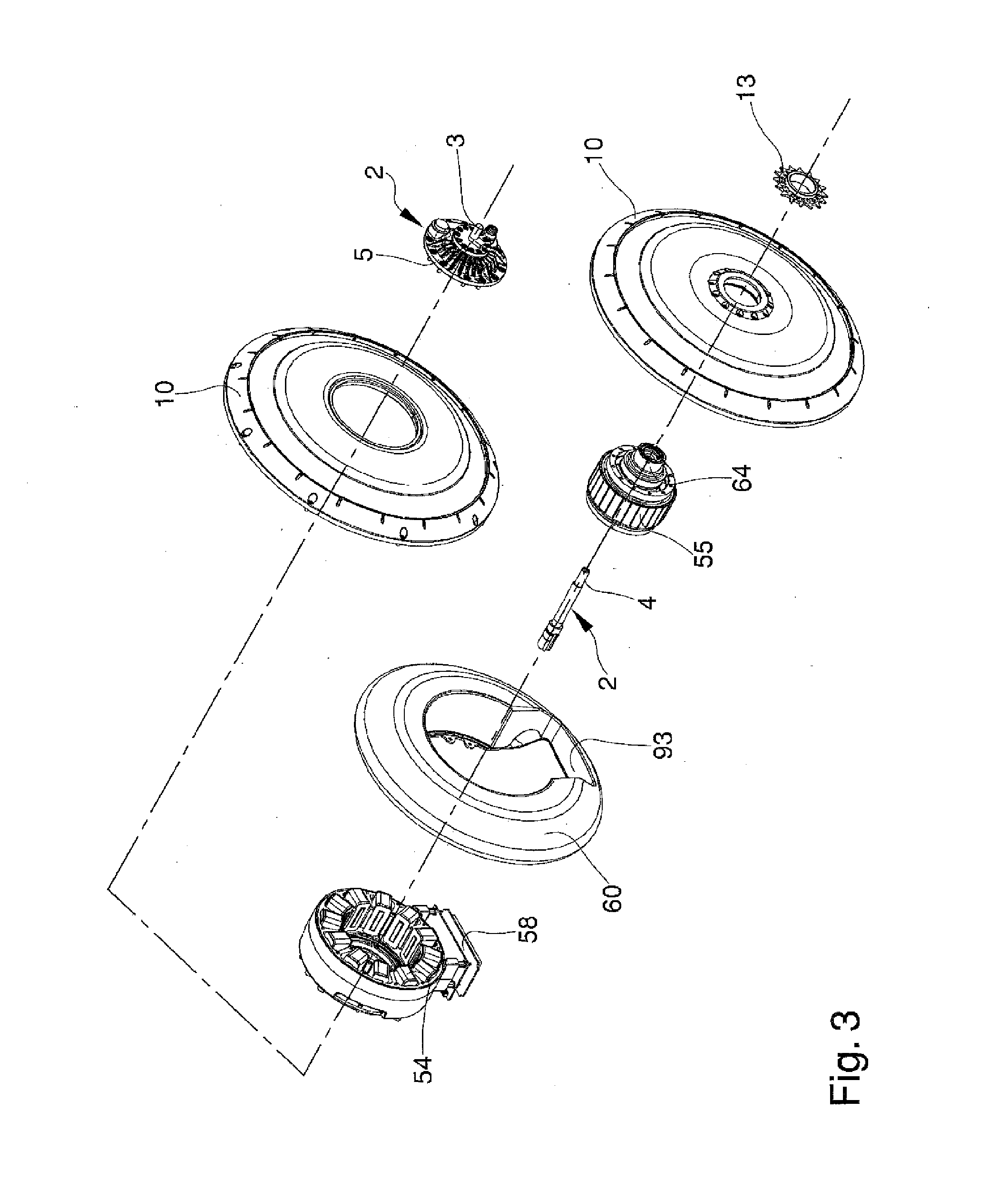
[0033]Other characteristics and advantages of the present invention will become apparent from the description of a preferred, but not exclusive, embodiment of a wheel for pedal-assisted bikes, illustrated by way of an indicative, but not limitative, example in the a...


PUM


Abstract

The wheel (1) for pedal-assisted bikes comprises:
    • a fixed structure (2) having attachment means for the attachment to the frame (T) of a bike (B) with a driving pedal crank (P);
    • a circle element (10, 11, 12) mounted on the fixed structure (2) in a revolving way around a main rotation axis (A);
    • a propulsion disk (13) mounted on the fixed structure (2) in a revolving way and drivable in rotation by the driving pedal crank (P);
    • motion transmission means (15, 16) for the transmission of the rotational motion from the propulsion disk (13) to the circle element (10, 11, 12), which comprise at least a first detection device (16) suitable for detecting the driving torque transmitted to the circle element (10, 11, 12) from the propulsion disk (13);
    • an electric motor (54, 55) associated with the fixed structure (2) and suitable for cooperating with the propulsion disk (13) to motorize the circle element (10, 11, 12); and
    • a processing and control unit (57, 58) operatively connected to the first detection device (16) and to the electric motor (54, 55) and suitable for controlling the activation of the electric motor (54, 55) according to the driving torque detected by the first detection device (16);
    • wherein the first detection device (16) comprises:
    • a measuring element (61, 62) which is subject to a stress condition due to the effect of the driving torque transmitted to the circle element (10, 11, 12) by the propulsion disk (13); and
    • at least a measuring sensor (63) which is arranged in correspondence to the measuring element (61, 62) and which is suitable for detecting the stress condition of the measuring element (61, 62) and for producing a corresponding electronic signal which can be processed by the processing and control unit (57, 58).

Description

TECHNICAL FIELD[0001]The present invention relates to a wheel for pedal-assisted bikes.BACKGROUND ART[0002]The pedal-assisted bikes are bikes equipped with an auxiliary electric motor having the following characteristics:[0003]maximum continuous rated power of the electric motor: 0.25 kW;[0004]motor power supply is gradually reduced and then interrupted when reaching 25 km / h;[0005]motor power supply interrupted before 25 km / h if the cyclist stops pedaling.[0006]The electric motor is controlled by means of a processing and control unit that manages the power delivery thereof according to the user's pedaling, balancing the insertion of the propulsion in a progressive manner starting from the very beginning of pedaling, so as to make this fluid and regular.[0007]For this purpose, the pedal-assisted bikes are equipped with a torque sensor arranged in correspondence of the pedals or with a speed sensor located in the pedal crank, or both.[0008]In traditional pedal-assisted bikes the elec...

Claims


Application Information

Patent Timeline
Patent Type & Authority Applications(United States)
IPC IPC(8): B62M6/65B60B27/00B60B27/02B60B27/04B60K7/00B62M6/50
CPCB62M6/65B60B27/0021B60B27/0068B60B27/023B60Y2200/13B60K7/0007B62M6/50B60K2007/0092B60B27/04
Inventor ZANFEI, ADRIANO
Owner C R D CENT RICERCHE DUCATI TRENTO
Why Eureka
Try Eureka