
X-ray photography device capable of photographing in various photography modes

Active Publication Date: 2016-03-17
LISTEM CORP
View PDF4 Cites 15 Cited by
  • Summary
  • Abstract
  • Description
  • Claims
  • Application Information

AI Technical Summary

Benefits of technology

The present invention is a stand type X-ray detecting device that can be used in different imaging modes, such as the standing mode and the table mode. It is designed to be easily switched between these modes and can be installed in narrow spaces without the need for separate installation of a table. The device includes a support frame and an actuator between the base frame and the support frame, allowing for free pivoting of the support frame within a predetermined angle range. The device also includes a wire connection structure with a closed loop shape to prevent damage to the wire when the device is switched between modes. The X-ray detector is installed to be movable in a front and rear direction and the table is tiltable in a vertical direction, making it easy to perform imaging in both modes. The control unit can simultaneously perform a sliding linear movement and a rotational movement of the support frame, reducing the number of control units and improving user convenience. A separate parking device is installed at the bottom of the table to securely mount the table in a tilted position.

Problems solved by technology

Therefore, there are problems in that a separate X-ray imaging apparatus dedicated for each imaging mode is necessary, and accordingly an installation cost excessively increases due to redundant installations of expensive X-ray imaging apparatuses, or an installation space is not efficiently utilized.

Method used


Image

  • X-ray photography device capable of photographing in various photography modes
  • X-ray photography device capable of photographing in various photography modes
  • X-ray photography device capable of photographing in various photography modes

Examples


second embodiment

[0078]Meanwhile, FIG. 9 is a perspective view of an X-ray imaging apparatus according to the present invention. FIG. 10 is a detail view illustrating a detailed part of a table tilting device of FIG. 9. Also, FIG. 11 is a usage state diagram illustrating a state in which a table is completely tilted up in order to perform imaging in a standing mode in the X-ray imaging apparatus of FIG. 9. FIG. 12 is a partial perspective view illustrating a state in which a lower end of a rotating leg portion of a table is parked in a parking device provided in a bottom portion. FIG. 13 is a partial perspective view illustrating a state in which a driving unit for a sliding linear movement is installed in a base frame.

[0079]Unlike the X-ray imaging apparatus of the first embodiment described above, the X-ray imaging apparatus according to the second embodiment of the present invention has a configuration in which the X-ray detecting device 100 and the table 300 form one set above a bottom portion 1...

first embodiment

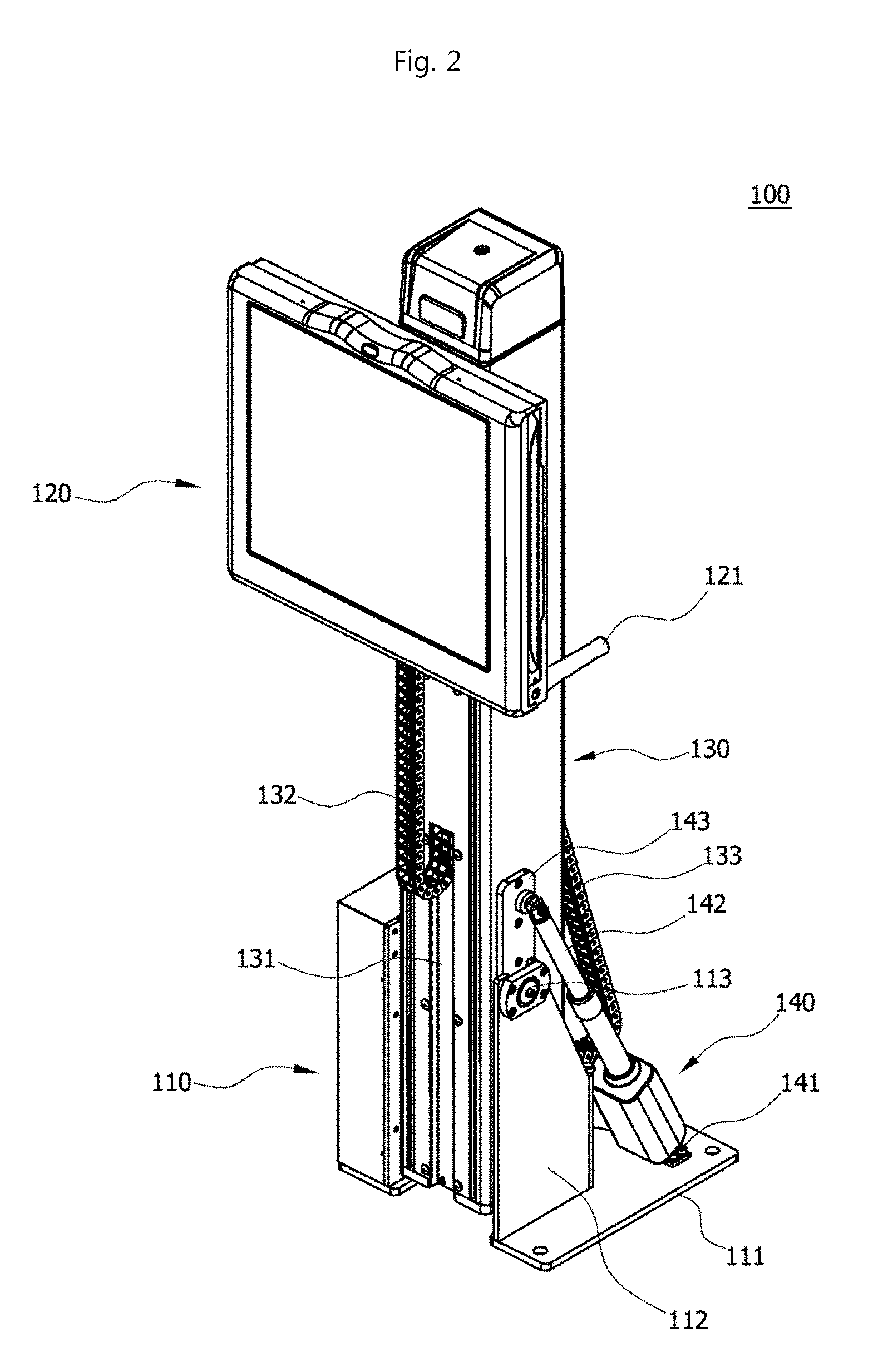
[0085]Also, the actuator (not illustrated) having the same shape as in the first embodiment described above is provided inside the base frame 110 such that the support frame 130 provided with the X-ray detector 120 can be pivoted in a predetermined angle range.

[0086]Also, as illustrated in FIG. 13, in the base frame 110, a driving unit configured to drive such that the base frame 110 slidably linearly reciprocates along an upper surface of the bottom portion 190 is installed.

[0087]The driving unit includes a driving motor 342 installed inside the base frame 110, a plurality of casters 344 that are rotatably installed at a lower end of the base frame 110 and move along the upper surface of the bottom portion 190 in a rolling manner, and a power transmission device 343 connecting the driving motor 342 and the caster 344 and configured to transmit power of the driving motor 342 to the caster 344. Also, the driving unit includes a guide unit configured to guide such that the caster 344 ...


PUM


Abstract

An X-ray photography device capable of readily photographing by switching to various photography modes such as a standing mode, a table mode and the like with one X-ray photography device is disclosed. To this end, the X-ray photographing device comprises: a base frame; a support frame pivotably coupled to one side of the base frame through a hinge shaft and on one side of which an X-ray detector for detecting X-rays irradiated from an X-ray generation device is slidably provided; and an actuator of which one end is rotatably fixed to the base frame and of which the other end is rotatably fixed to the support frame spaced at a predetermined distance from the hinge shaft, and which pivots the support frame around the hinge shaft within a predetermined angle range while moving a driving shaft therein forward and backward by pneumatic or hydraulic pressure supplied from the outside.

Description

TECHNICAL FIELD[0001]The present invention relates to an X-ray imaging apparatus capable of easily performing imaging by switching a mode to various imaging modes such as a standing mode and a table mode using one X-ray imaging apparatus.BACKGROUND ART[0002]In general, X-ray imaging apparatuses are medical apparatuses that are used for radiographic examinations using images of internal diseases of human bodies, and analyze whether a bone of human bodies is damaged in a chest, a head, gastrointestinal tracts, vertebrae and injured areas of human bodies through X-rays.[0003]In general, such X-ray imaging apparatuses have different imaging modes, a standing mode in which imaging is performed while a patient stands up and a table mode in which imaging is performed while the patient is lying on a table. Here, when imaging is performed in the standing mode, imaging is performed while an X-ray detector mounted to be vertically movable on a wall surface or a post positioned at a side opposi...

Claims


Application Information

Patent Timeline
IPC IPC(8): A61B6/00
CPCA61B6/4429A61B6/447A61B6/0407A61B6/4452A61B6/0487A61B6/00A61B6/04A61B6/08
Inventor MOON, CHANG HOMOON, JUNG HYUNMOON, SANG JINSHIN, JUNG WOOK
Owner LISTEM CORP
Learn More