

Tire
- Summary
- Abstract
- Description
- Claims
- Application Information
AI Technical Summary
Benefits of technology
Problems solved by technology
Method used
Image

Examples
first embodiment
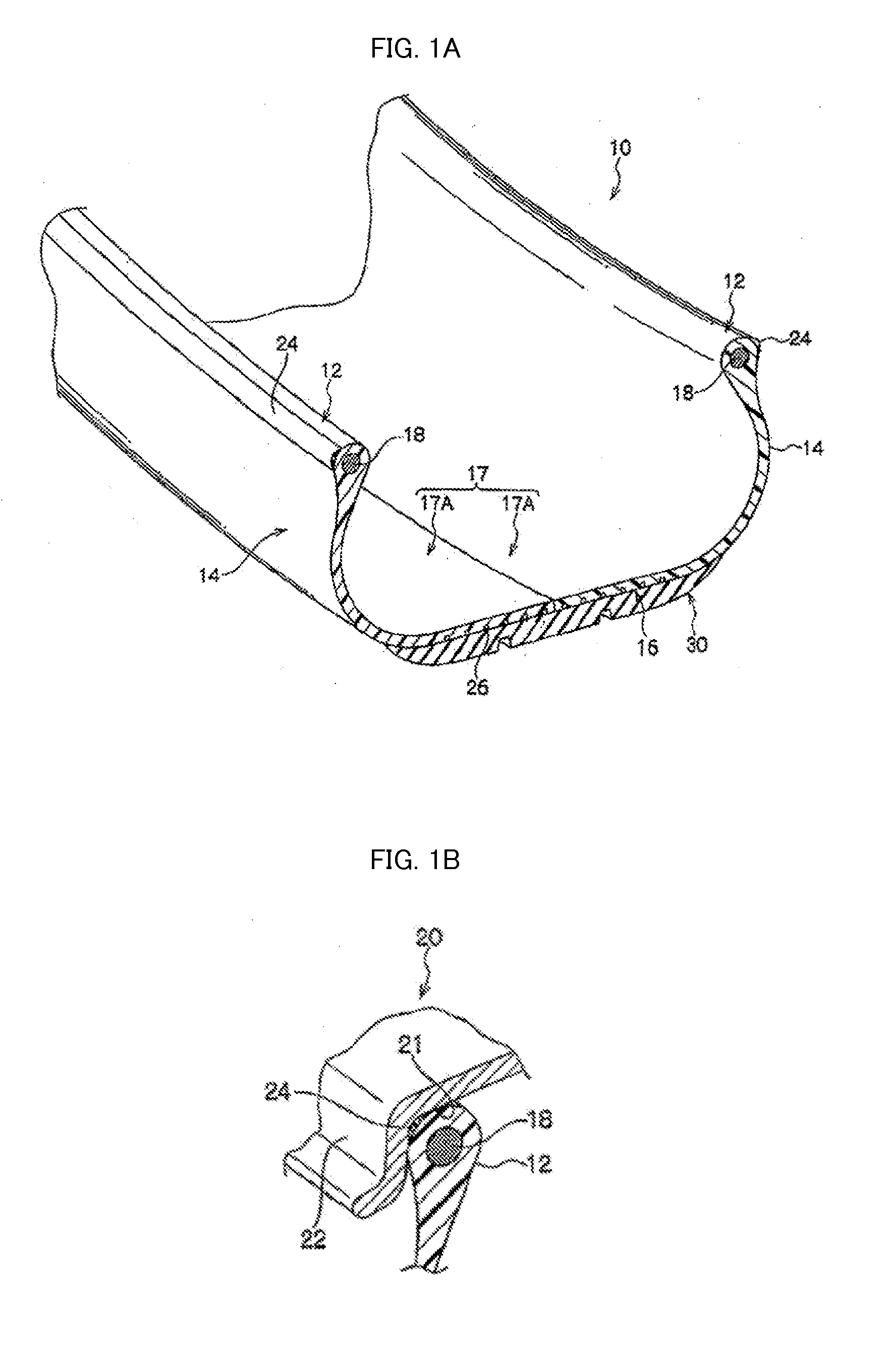
[0179]First, a tire 10 according to a first embodiment of the invention will be explained with reference to FIG. 1A and FIG. 1B. FIG. 1A is a perspective view illustrating a cross-section of a portion of the tire according to the first embodiment of the invention. FIG. 1B is a cross-sectional view of a bead portion that has been fitted onto a rim. As illustrated in FIG. 1A, the tire 10 according to the first embodiment has a cross-sectional shape substantially similar to cross-sectional shapes of ordinary conventional rubber-made pneumatic tires.
[0180]The tire 10 according to the first embodiment of the invention includes a tire case 17 including a pair of bead portions 12 each of which is in contact with a bead seat 21 and a rim flange 22 of a rim 20, side portions 14 that respectively extend tire radial direction outward from the bead portions 12, and a crown portion 16 that connects a tire radial direction outer end of one of the side portions 14 with a tire radial direction oute...
second embodiment
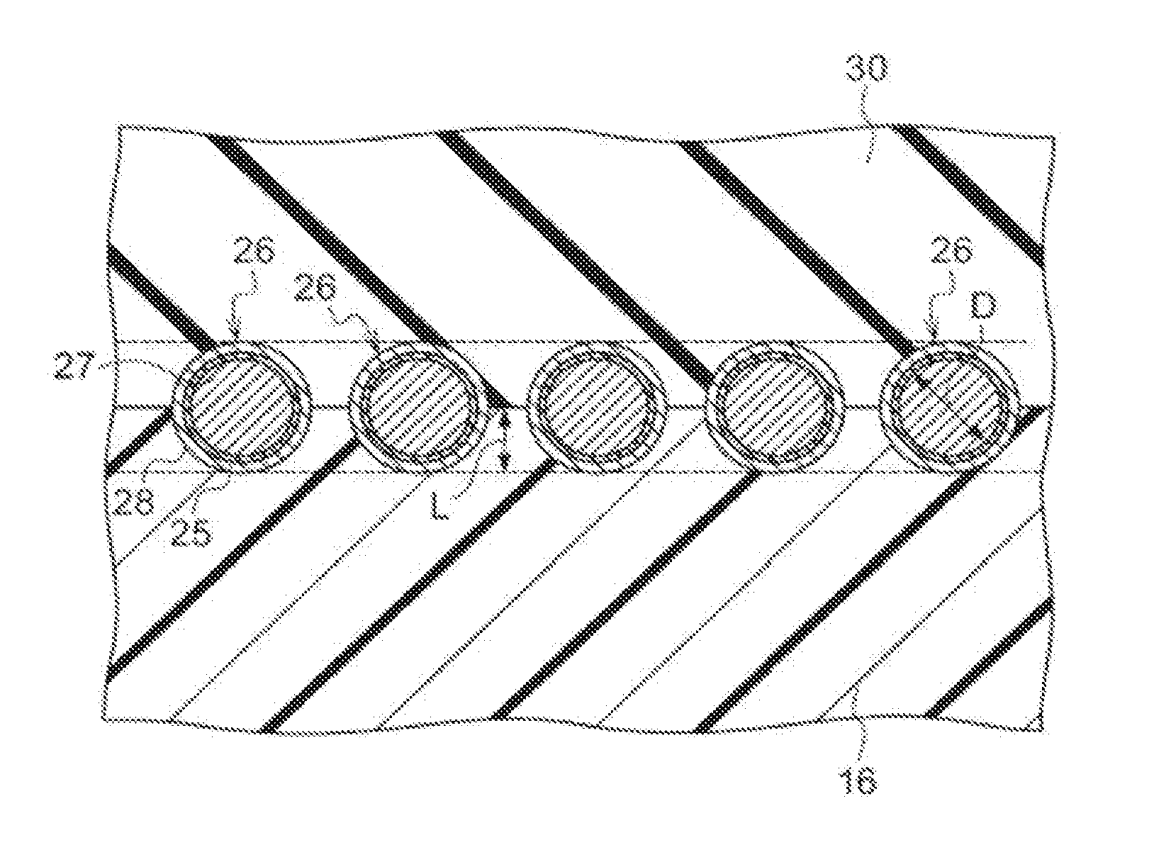
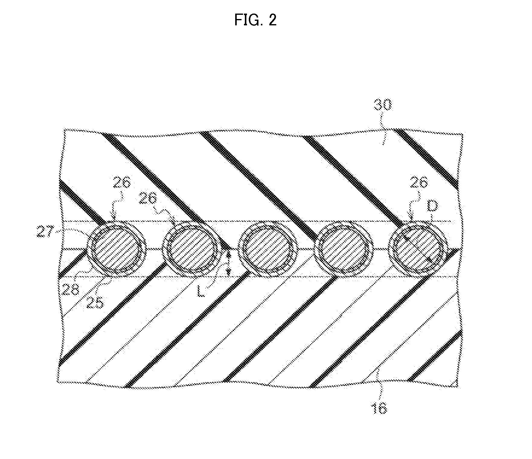
[0223]Next, the tire according to a second embodiment of the invention will be described with reference to FIG. 4. FIG. 4 is a cross-sectional view taken along the tire rotation axis and illustrating a state in which a reinforcing cord covering layer in which a reinforcing metal cord member is embedded is on the crown portion of the tire case of the tire according to a second embodiment.
[0224]As illustrated in FIG. 4, the tire according to the second embodiment of the invention includes a reinforcing cord covering layer 29 in which the steel cord 27 (the reinforcing metal cord member) is embedded in the surface of the crown portion 16 of the tire case, in which a tread 30 is disposed on the reinforcing cord covering layer 29. The tire according to the second embodiment of the invention has a configuration similar to that of the first embodiment, except in the above points. The same reference numerals are herein allocated to configurations similar to those of the first embodiment.
[02...
example 1
[0244]In accordance with the resin-covered cord forming process described above, a multifilament having an average diameter ø of 1.15 mm (a twisted cord formed of twisted monofilaments having ø of 0.35 mm (made of steel, strength: 280 N, elongation degree: 3%)) was coated with a solvent-based adhesive A-1 described in Table 1, and then, dried in a drying furnace at 70° C. for one minute to form an adhesion layer having an average layer thickness of 10 μm on an outer circumference of the multifilament. Next, the outer circumference of the multifilament having the formed adhesion layer was coated with a resin N-1 extruded by a extruder, and then the multifilament was cooled, whereby a metal reinforcing cord was obtained in which an outer circumference of the multifilament was covered with the composition N-1 via the adhesion layer containing the solvent-based adhesive A-1.
[0245]A tire was formed using the obtained reinforcing metal cord according to a method similar to the first embod...
PUM
| Property | Measurement | Unit |
|---|---|---|
| Thickness | aaaaa | aaaaa |
| Thickness | aaaaa | aaaaa |
| Thermoplasticity | aaaaa | aaaaa |
Abstract
Description
Claims
Application Information