Electromagnetic Valve Control Unit and Internal Combustion Engine Control Device Using Same
a control unit and electric valve technology, applied in the direction of electric control, fuel injection apparatus, charge feed system, etc., can solve the problems of large deviation of the injection amount of fuel in one combustion stroke from the target fuel injection amount, and the relative increase of the variation amount to the fuel injection amount for each combustion strok
- Summary
- Abstract
- Description
- Claims
- Application Information
AI Technical Summary
Benefits of technology
Problems solved by technology
Method used
Image
Examples
first embodiment
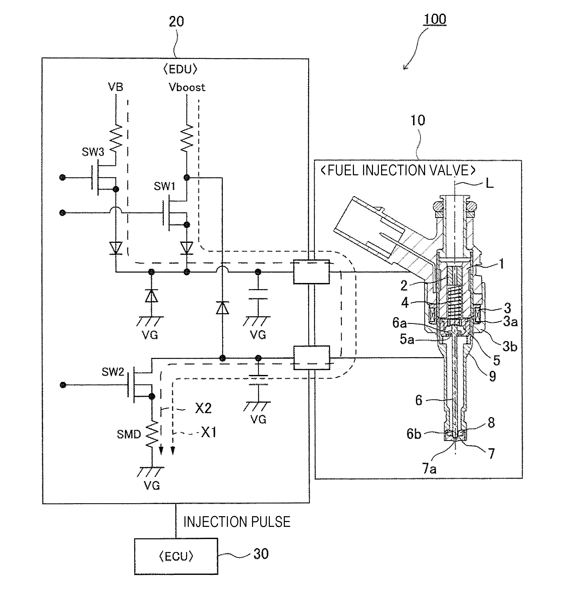
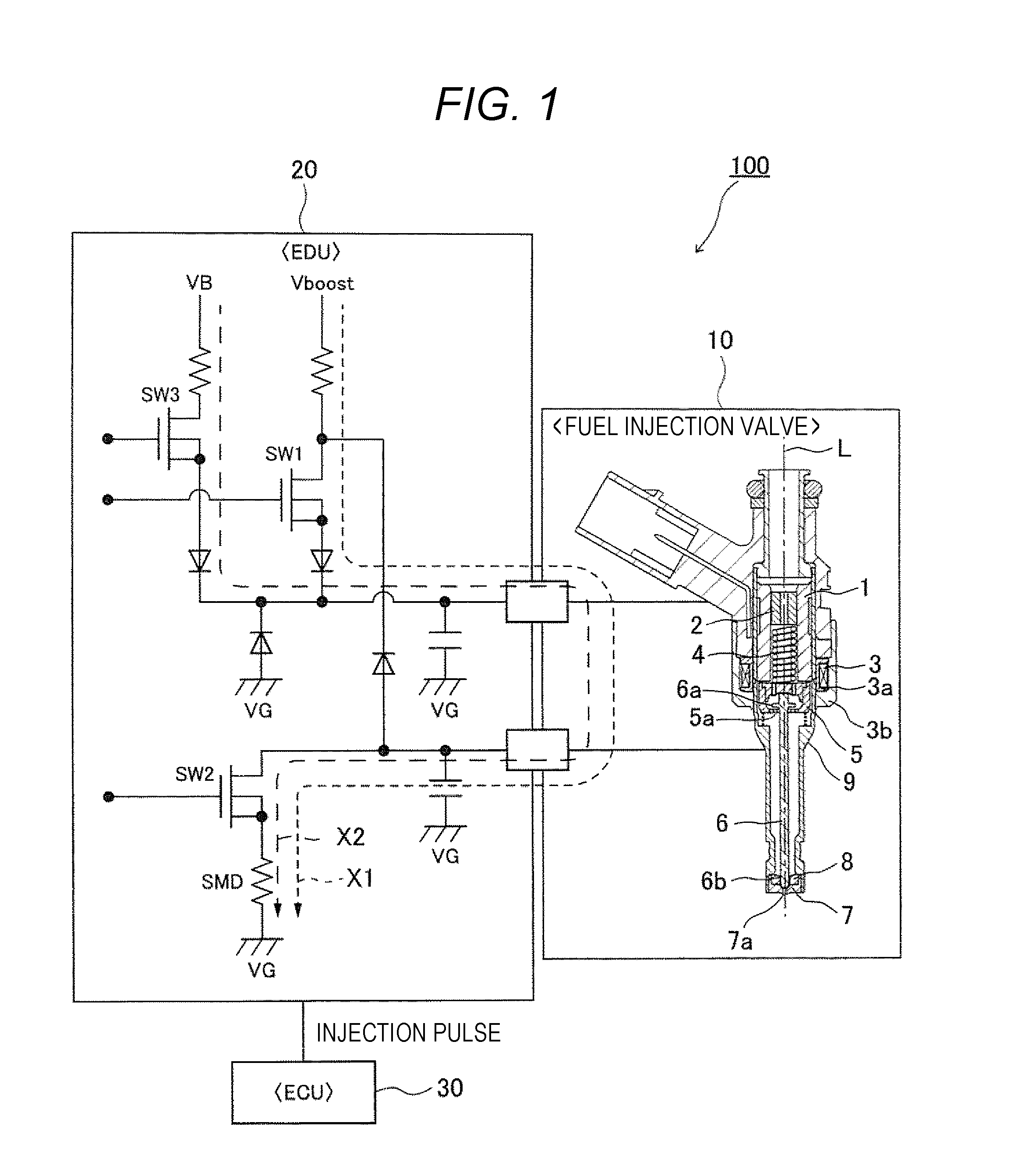
[0035]FIG. 1 is an entire configuration diagram illustrating an entire configuration of a fuel injection device to which an internal combustion engine control device using a first embodiment of an electromagnetic valve control unit according to the present invention is applied.
[0036]A fuel injection device 100 illustrated in the drawing mainly includes an electromagnetic fuel injection valve (electromagnetic valve) 10, an engine drive unit (EDU) (drive circuit) 20, and an engine control unit (ECU) (internal combustion engine control device) 30. The ECU 20 and the EDU 30 may be configured as separated units and may be configured to be integrated with each other.
[0037]The electromagnetic fuel injection valve 10 mainly includes a cylindrical body 9, a cylindrical fixed core 1 fixedly arranged in the cylindrical body 9, a solenoid 3 wound around a bobbin 3a arranged outside the fixed core 1 via the cylindrical body 9, a movable element 5 arranged relatively movably in a direction of an ...
second embodiment
[0081]In the first embodiment, the form in which the current signal digitized by the A / D converter is multiplied by the Hanning Window and a second-order difference of a calculation result thereof is calculated was described.
[0082]By the way, when a second-order difference of an output signal of the following formula (3) obtained by multiplying a signal Ut by the Hanning Window (filter coefficient Ft) is calculated, deformation shown by the following formula (4) can be executed.
[MathematicalFormula3]Yt=∑i=0lFiUt-i(3)[MathematicalFormula4]Yt+i-2Yt+Yt-1Δ2=∑i=0lFiUt+1-i-2∑i=0lFiUt-i+∑i=0lFiUt-1-iΔ2=(F0Ut+1+F1Ut+∑i=2lFiUt+1-i)-2(F0Ut+∑i=1l-1FiUt-i+FlUt-l)+(∑i=0l-2FiUt-1-i+Fl-1Ut-i+FlUt-1-l)Δ2=(F0Ut+1+F1Ut)-2(F0Ut+FlUt-l)+(Fj-1Ut-l+FlUt-1-l)Δ2+∑i=1l-1Fi+1Ut-i-2∑i=1l-1FiUt-i+∑i=1l-1Fi-1Ut-iΔ2=(F0Ut+1+F1Ut)-2(F0Ut+FjUt-l)+(Fl-1Ut-l+FlUt-1-l)Δ2+∑i=1l-1Fi+1-2Fi+Fi-1Δ2Ut-i(4)
[0083]Here, as illustrated in FIGS. 8 and 13(a), because filter coefficients of both ends of the Hanning Window may be ...
third embodiment
[0096]An output Y when a signal U is input to the filter having the filter coefficient Fi illustrated in FIGS. 13(a) and 13(b) or FIGS. 17(a) to 17(c) is represented by the formula (3). The formula (3) can be represented as illustrated in FIG. 18 or 19. That is, as illustrated in FIG. 19, the formula (3) represents taking a correlation of a reference pattern having the same characteristic as the filter and the input signal U. In FIG. 19, a symbol in which a mark is surrounded with a circle represents an operation to take a correlation of inputs Ut, . . . , and Ut−1 and F0, . . . , and F1.
[0097]In addition, when a peak (extreme value) is detected from the correlation of the reference pattern and the input signal U, this means that the reference patterns are shifted like tk−2, tk−1, tk, tk+1, and tk+2 (refer to FIG. 20), correlations with the input signals U are calculated at positions of the individual reference patterns, and a position (tk in FIG. 20) where the calculated correlatio...
PUM
 Abstract
Description
Claims
Application Information
 - R&D
- Intellectual Property
- Life Sciences
- Materials
- Tech Scout
- Unparalleled Data Quality
- Higher Quality Content
- 60% Fewer Hallucinations
Browse by: Latest US Patents, China's latest patents, Technical Efficacy Thesaurus, Application Domain, Technology Topic, Popular Technical Reports.
© 2025 PatSnap. All rights reserved.Legal|Privacy policy|Modern Slavery Act Transparency Statement|Sitemap|About US| Contact US: help@patsnap.com


