Cable connector assembly with cable wires made of heat-resisting material

a technology of heat-resistance material and cable wire, which is applied in the direction of electrically conductive connections, conductors, laser beam welding apparatuses, etc., can solve the problems of damage to the outer insulative layers of adjacent single wires, and achieve the effect of preventing damage to single wires

Active Publication Date: 2016-03-17
FOXCONN INTERCONNECT TECH LTD
View PDF10 Cites 53 Cited by
  • Summary
  • Abstract
  • Description
  • Claims
  • Application Information

AI Technical Summary

Benefits of technology

[0007]To achieve the above-mentioned object, a cable connector assembly includes an internal printed circuit board (PCB), a cable electrically connected to the PCB and defining a plurality of coaxial wires and a plurality of single wires, and a housing receiving the PCB. The PCB defines a front end portion, an opposite rear end portion, and a middle portion. The PCB includes a plurality of first conductive pads disposed on the front end portion, a plurality of second conductive pads disposed on the rear end portion and connected to the cable, and a plurality of third conductive pads disposed behind the second conductive pads. The PCB has an upper surface and an opposite lower surface. Each coaxial wire has a first inner conductor soldered to the corresponding second conductive pad, an inner insulative layer enclosing the first inner conductor, a metal braided layer enclosing the inner insulative layer and soldered to the corresponding third conductive pads, and an outer insulative layer enclosing the metal braided layer. Some of the coaxial wires and single wires adjacent to and arranged in a row with the coaxial wires are disposed on at least one surface of the PCB. Each single wire has a second conductor soldered to the corresponding second conductive pads, a first insulative layer enclosing the second conductor, and a second insulative layer enclosing the first insulative layer. The first insulative layer is made of heat-resisting material to prevent the adjacent single wires from being damaged when soldering the metal braided layer of the coaxial wires.
[0008]According to the present invention, the first insulative layer of the single wire adjacent to the coaxial wires is further enclosed by the second insulative layer. It efficiently prevents the single wires from damage when soldering the metal braided layer of the coaxial wires.

Problems solved by technology

When soldering the coaxial wires, outer insulative layers of adjacent single wires might be damaged.

Method used


Image

  • Cable connector assembly with cable wires made of heat-resisting material
  • Cable connector assembly with cable wires made of heat-resisting material
  • Cable connector assembly with cable wires made of heat-resisting material

Examples


Embodiment Construction

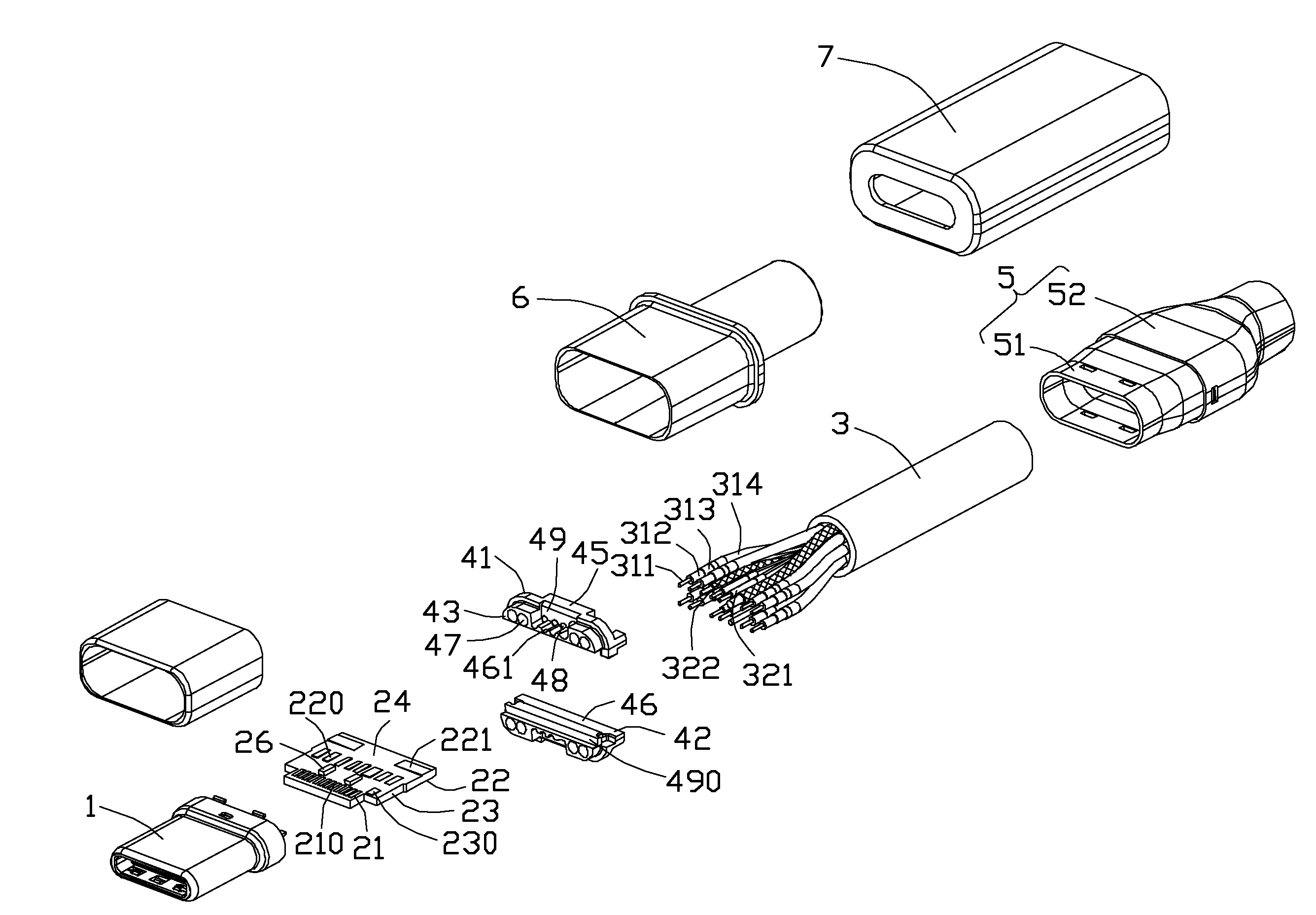
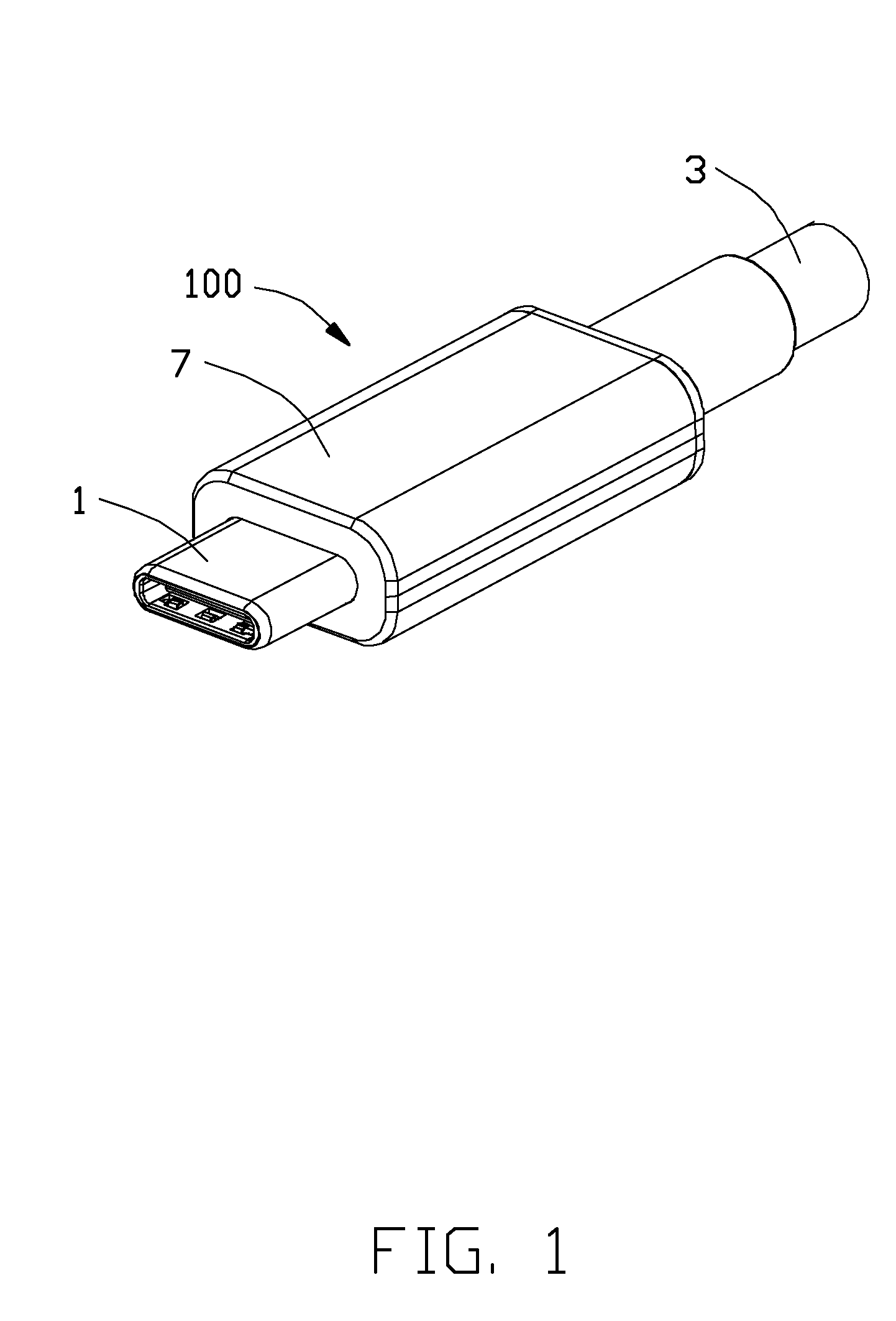
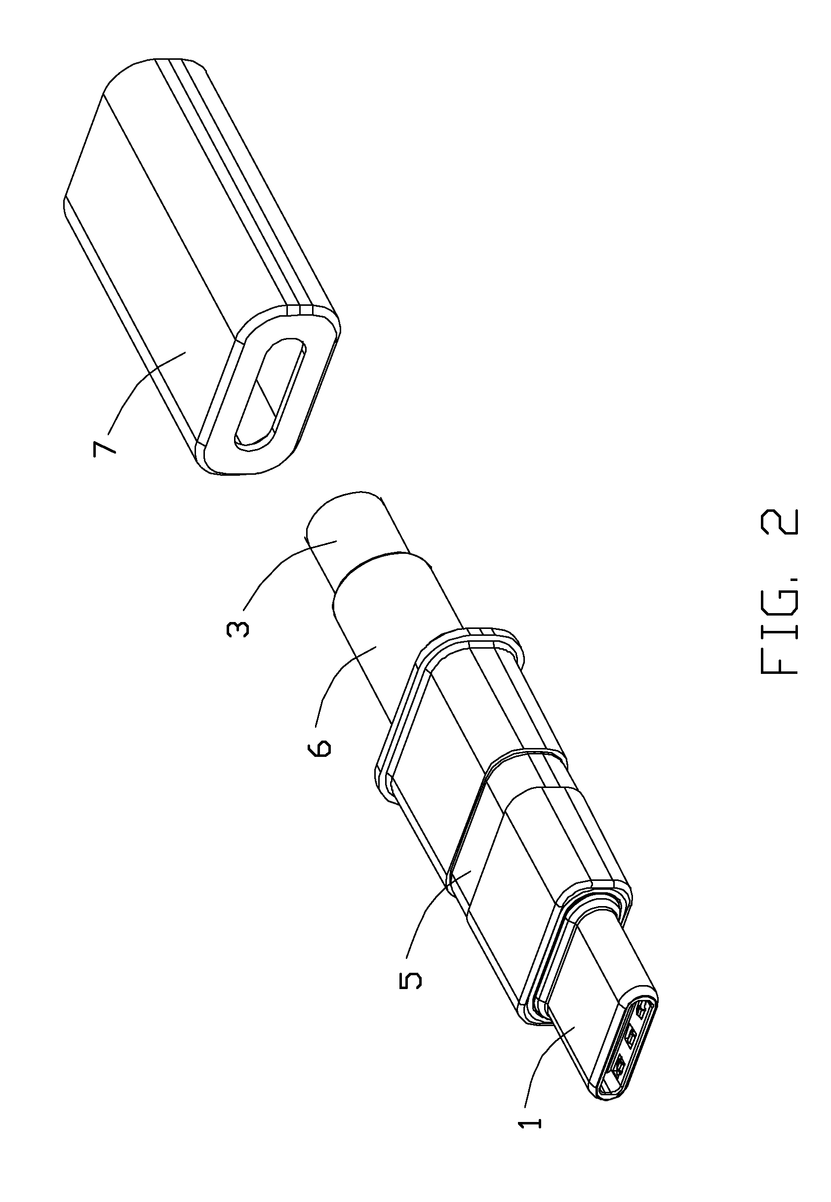
[0019]Referring to FIGS. 1 to 7, a cable connector assembly 100 in accordance with the present invention for mating with a mating connector (not shown) comprises a mating member 1, an inner printed circuit board (PCB) 2 connected to the mating member 1, a cable 3 electrically connected with the PCB 2, a spacer 4 locating the cable 3, an inner member 5 enclosing part of the cable 3 and the mating member 1, a strain relief 6 molded out of the cable 3 and the inner member 5, and a housing 7 disposed outside. The cable connector assembly 100 can be mated with the mating connector in two different directions to achieve the same function.

[0020]Referring to FIGS. 9 and 10, the mating member 1 comprises an insulative housing 11, a plurality of conductive terminals 12 received in the insulative housing 11 and arranged in two rows spaced apart from each other in a vertical direction, a latch 13 disposed between the two rows of conductive terminals 12 for latching with the mating connector, an...


PUM

PropertyMeasurementUnit
conductiveaaaaaaaaaa
adhesionaaaaaaaaaa
dimensionaaaaaaaaaa

Abstract

A cable connector assembly includes a PCB defining some second conductive pads disposed on a rear end portion of the PCB and some third conductive pads disposed behind the second conductive pads, a cable defining a number of coaxial wires and single wires, and a housing. Each coaxial wire has a first inner conductor, an inner insulative layer enclosing the first inner conductor, a metal braided layer soldered to the corresponding third conductive pads, and an outer insulative layer. Part of the coaxial wires and single wires adjacent to the coaxial wires are disposed on at least one surface of the PCB. Each single wire has a second conductor, a first insulative layer, and a second insulative layer. The first insulative layer is made of heat-resisting material to prevent the adjacent single wires from being damaged when soldering the metal braided layer of the coaxial wires.

Description

BACKGROUND OF THE INVENTION[0001]1. Field of the Invention[0002]The present invention relates to a cable connector assembly, and more particularly to a structure of core wires thereof.[0003]2. Description of Related Arts[0004]U.S. Pat. No. 8,133,071, issued on Mar. 13, 2012, shows a cable connector assembly including a flat cable and a flexible printed circuit. The cable defines a row of core wires and an insulative layer enclosing the core wires. The core wires comprise a plurality of coaxial cables and a plurality of single wires. The flexible printed circuit comprises a plurality of pads arranged in a line and a lengthwise grounding portion separated from the pads. Each coaxial cable comprises an inner conductor connected to a corresponding pad and an outer conductor connected to the grounding portion. The single wires comprise a plurality of power wires connected to corresponding pads and a plurality of grounding wires connected to the grounding portion. The coaxial cables and t...

Claims


Application Information

Patent Timeline
Patent Type & Authority Applications(United States)
IPC IPC(8): H01R9/05B23K1/00H01R43/02
CPCH01R9/0515B23K1/0016H01R43/0235B23K26/22B23K26/24B23K26/32B23K2101/38
Inventor WU, JERRYCHEN, JUNMENG, FAN-BO
Owner FOXCONN INTERCONNECT TECH LTD
Why Eureka
Try Eureka