
Liquid Cooled Metal Core Printed Circuit Board

a printed circuit board and metal core technology, applied in the field of liquid cooling metal core printed circuit boards, can solve the problems of increased thermal dissipation rates, simplified production methods, and higher possible input temperatures for cooling fluids, so as to reduce the number of components required, reduce thermal bottlenecks, and increase thermal dissipation rates

Active Publication Date: 2016-03-17
DONOFRIO NICHOLAS MICHAEL
View PDF21 Cites 31 Cited by
  • Summary
  • Abstract
  • Description
  • Claims
  • Application Information

AI Technical Summary

Benefits of technology

The present patent is about a system that cools down a specific component by using liquid coolant. This system is designed to minimize the space between the component and the coolant, which increases the heat dissipation and allows for higher input temperatures for the coolant. This results in faster cooling, lower energy consumption, and simplified production methods and lower costs.

Problems solved by technology

This may result in increased thermal dissipation rates, higher possible input temperatures for cooling fluids, lower energy consumption, simplified production methods, and lower production costs.

Method used


Image

  • Liquid Cooled Metal Core Printed Circuit Board
  • Liquid Cooled Metal Core Printed Circuit Board
  • Liquid Cooled Metal Core Printed Circuit Board

Examples


Embodiment Construction

[0016]In the following detailed description, reference is made to the accompanying drawings, which form a part hereof. In the drawings, similar symbols typically identify similar components, unless context dictates otherwise. The illustrative examples described herein are not meant to be limiting. Other examples may be utilized, and other changes may be made, without departing from the spirit or scope of the subject matter presented here. It will be readily understood that the aspects of the present disclosure, as generally described herein, and illustrated in the Figures, may be arranged, substituted, combined, and designed in a wide variety of different configurations, all of which are explicitly contemplated and make part of this disclosure.

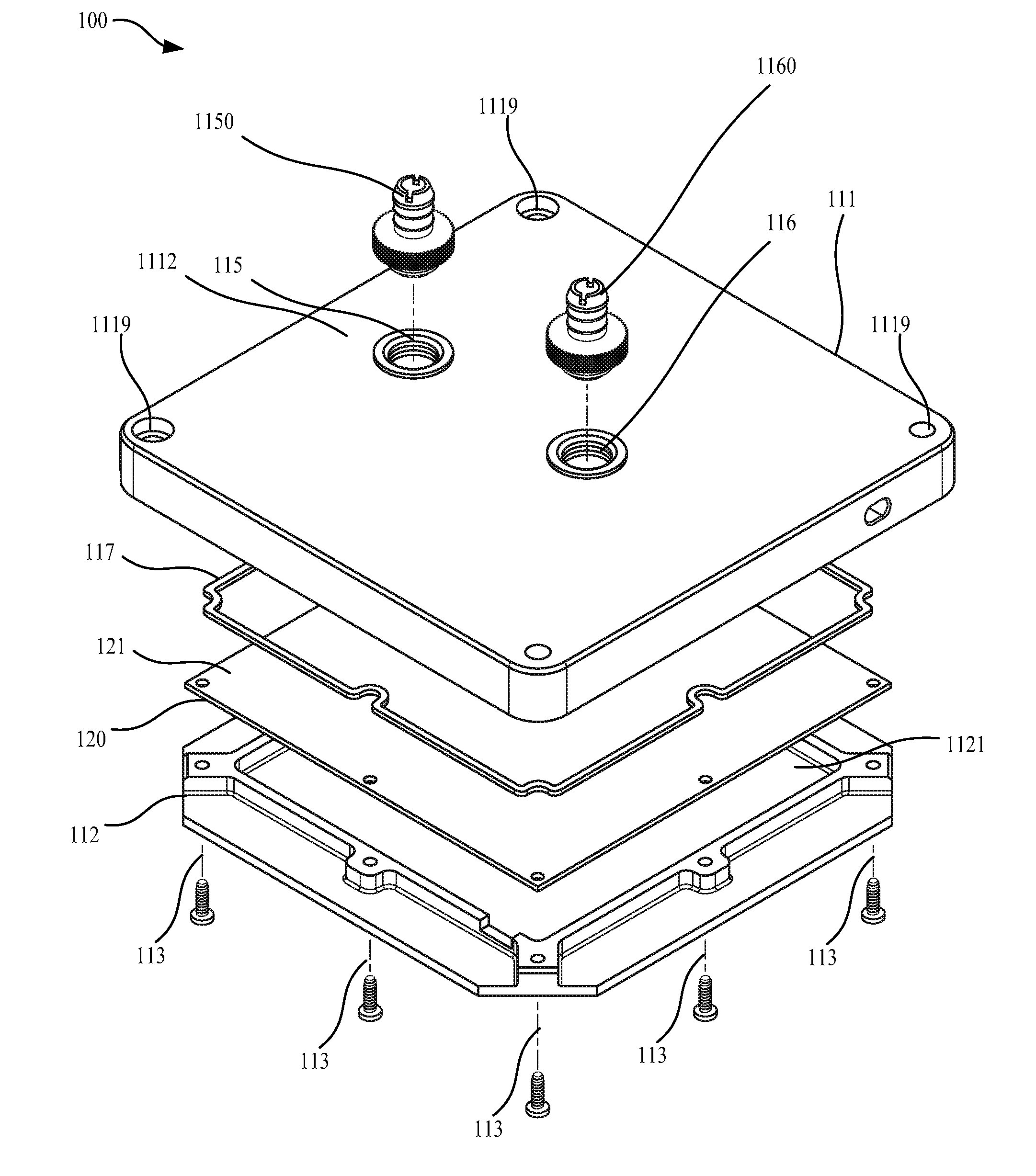
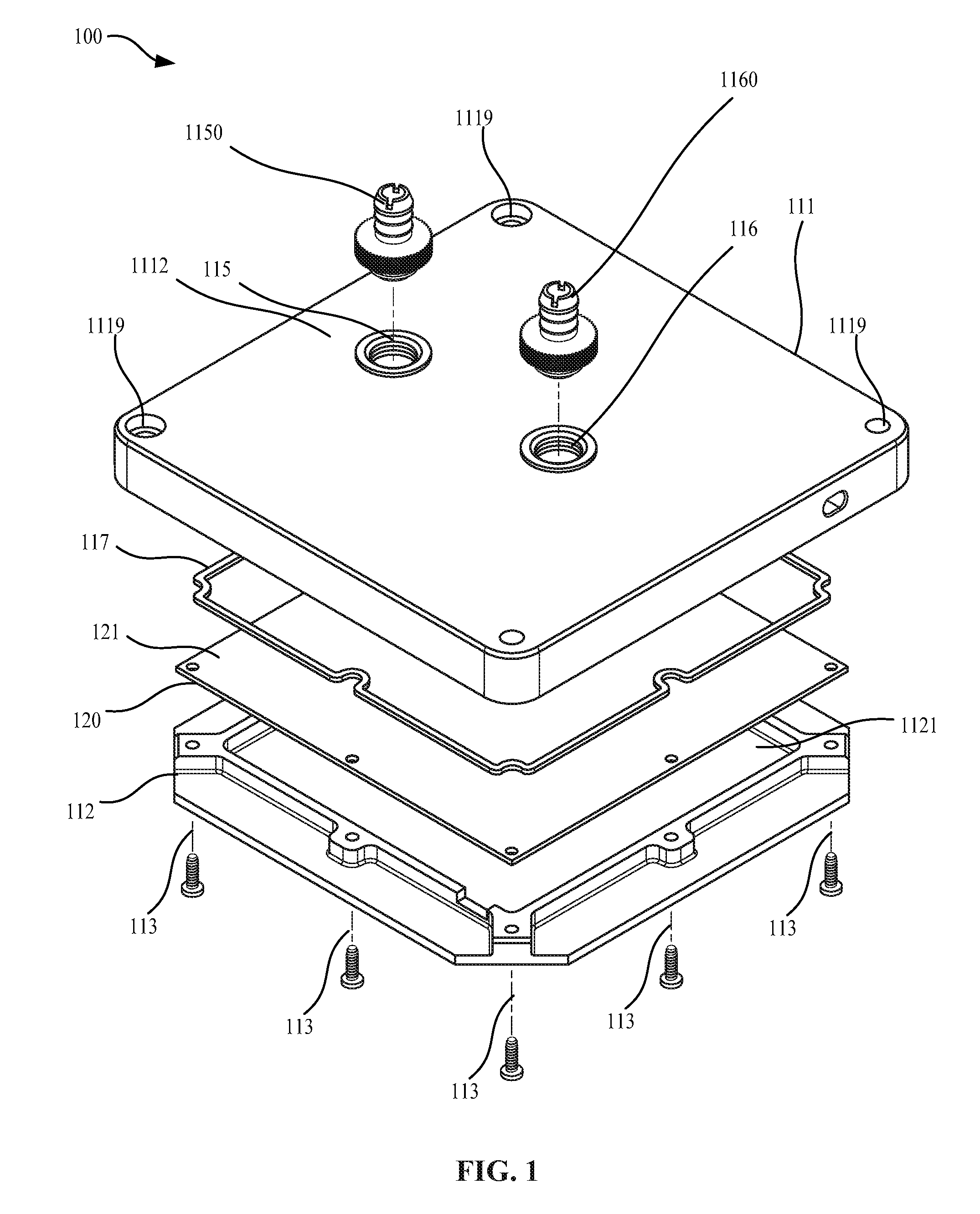
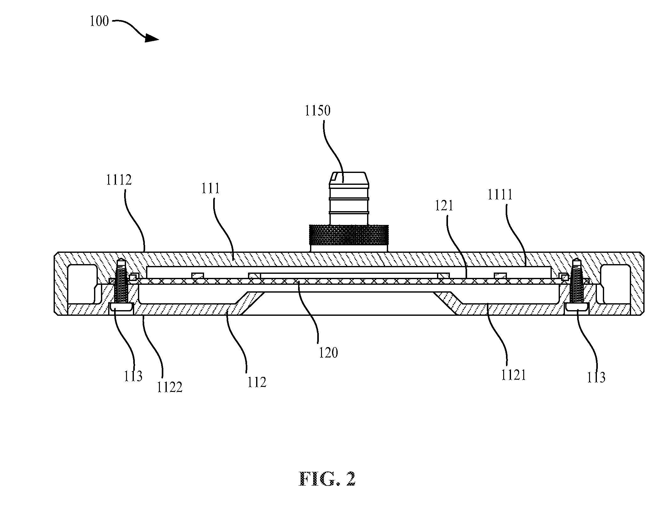
[0017]Turning to the figures in detail, FIG. 1 and FIG. 2 depict an example direct liquid cooled MCPCB system 100. The direct liquid cooled MCPCB system 100 may be comprised of a liquid cavity creating component 111, a MCPCB cover 112, a faste...


PUM


Abstract

The present disclosure further contemplates a system and method that cools metal core printed circuit boards by circulating a liquid coolant so that it contacts the base metal of the metal core printed circuit board. In one example the present disclosure contemplates a direct liquid cooled MCPCB system that may include a liquid cavity creating component coupled to the base plate of a MCPCB allowing a liquid coolant to come into contact with the base plate of the MCPCB for cooling of the MCPCB. The direct liquid cooled MCPCB system may minimize thermal bottlenecks between the electrical components and the cooling fluid while reducing the number of components required in previous liquid cooled electronics systems.

Description

RELATED APPLICATIONS[0001]This application claims priority under 35 U.S.C. §119 based on U.S. Provisional Application No. 62 / 050,488, filed on Sep. 15, 2014 and U.S. Provisional Application No. 62 / 051,383, filed on Sep. 17, 2014. The disclosure of both U.S. Provisional Application No. 62 / 050,488 and U.S. Provisional Application No. 62 / 051,383 are incorporated herein by reference.FIELD OF INVENTION[0002]The present disclosure contemplates a system and apparatus that cools metal core printed circuit boards. The present disclosure further contemplates a system and method that cools metal core printed circuit boards by circulating a liquid coolant so that it contacts the base metal of the metal core printed circuit board.BACKGROUND[0003]There have been a number of advancements in the field of thermal management for electronic circuit boards. One innovation has been the Metal Core Printed Circuit Board (“MCPCB”). This approach utilizes a layer of thermal conductive metal, such as copper ...

Claims


Application Information

Patent Timeline
Patent Type & Authority Applications(United States)
IPC IPC(8): H05K1/02
CPCH05K1/0203H01L33/648H05K1/0209H05K1/05H05K3/0061H05K7/20218H05K2201/064H05K2201/10409H05K2201/10969
Inventor D'ONOFRIO, NICHOLAS, MICHAEL
Owner DONOFRIO NICHOLAS MICHAEL
Learn More