
Integrated cement delivery system for bone augmentation procedures and methods

a bone augmentation and cement delivery technology, applied in the field of implants for bone augmentation procedures, can solve the problems of increasing the risk of cement leakage, and the pressure required to inject cement easily reaching the human physical limi

Active Publication Date: 2016-03-24
BAROUD GAMAL
View PDF1 Cites 26 Cited by
  • Summary
  • Abstract
  • Description
  • Claims
  • Application Information

AI Technical Summary

Benefits of technology

The present invention provides methods for injecting bone cement, extracting marrow, and rinsing marrow within a vertebra with a reduced risk of accidentally damaging the nervous system. The methods involve creating a pressure gradient between the injection and aspiration steps or between the inflation and removal steps to guide the displacement of bone fluid and the flow of bone cement or between the introduction of a negative pressure through the second passage and the application of a negative pressure through the first passage, respectively. These methods allow for safer and more effective procedures for preparing bones in which bone marrow and other fluids are present.

Problems solved by technology

Unfortunately, the pressure required to inject cement can easily reach values beyond human physical limit.
A number of pressure-controlled devices are available to increasing the pressure applied to the cement for delivery, however such devices may increase the risk of cement leakage because of a lack of control on the cement flow rate.
It is also known to lower the cement viscosity to ease the injection, however such an approach may also generally increase the risk of cement leakage.
While most cement leaks are inconsequential, every leak nevertheless exposes patients to serious risks, such as spinal cord and nerve root compression, pulmonary embolism, and possibly even death.
Physicians often use suggestive methods such as visual and / or tactile inspection to evaluate whether the viscosity of cement is adequate for injection, such methods being generally imprecise and not easily reproducible.

Method used


Image

  • Integrated cement delivery system for bone augmentation procedures and methods
  • Integrated cement delivery system for bone augmentation procedures and methods
  • Integrated cement delivery system for bone augmentation procedures and methods

Examples


Embodiment Construction

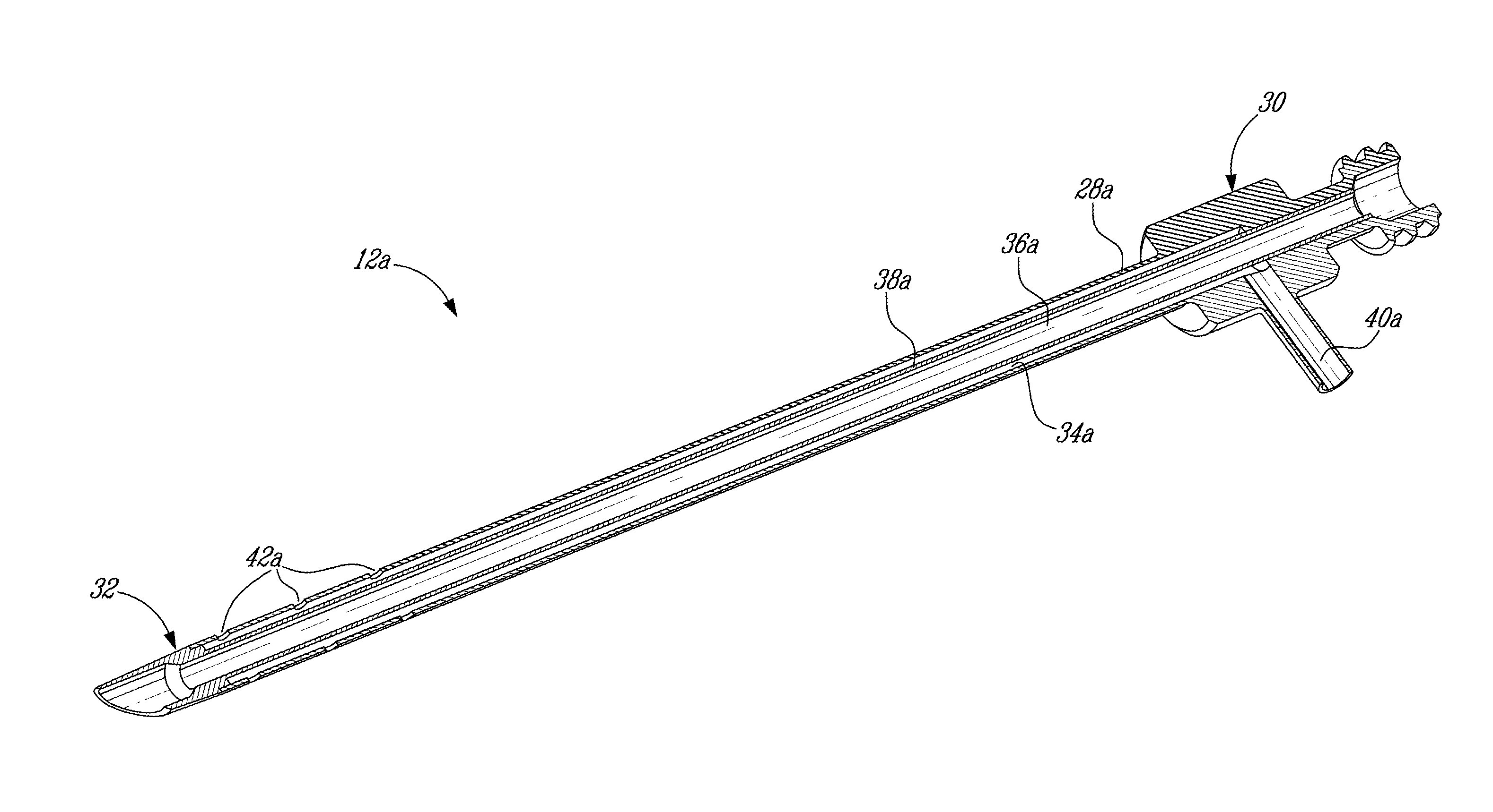
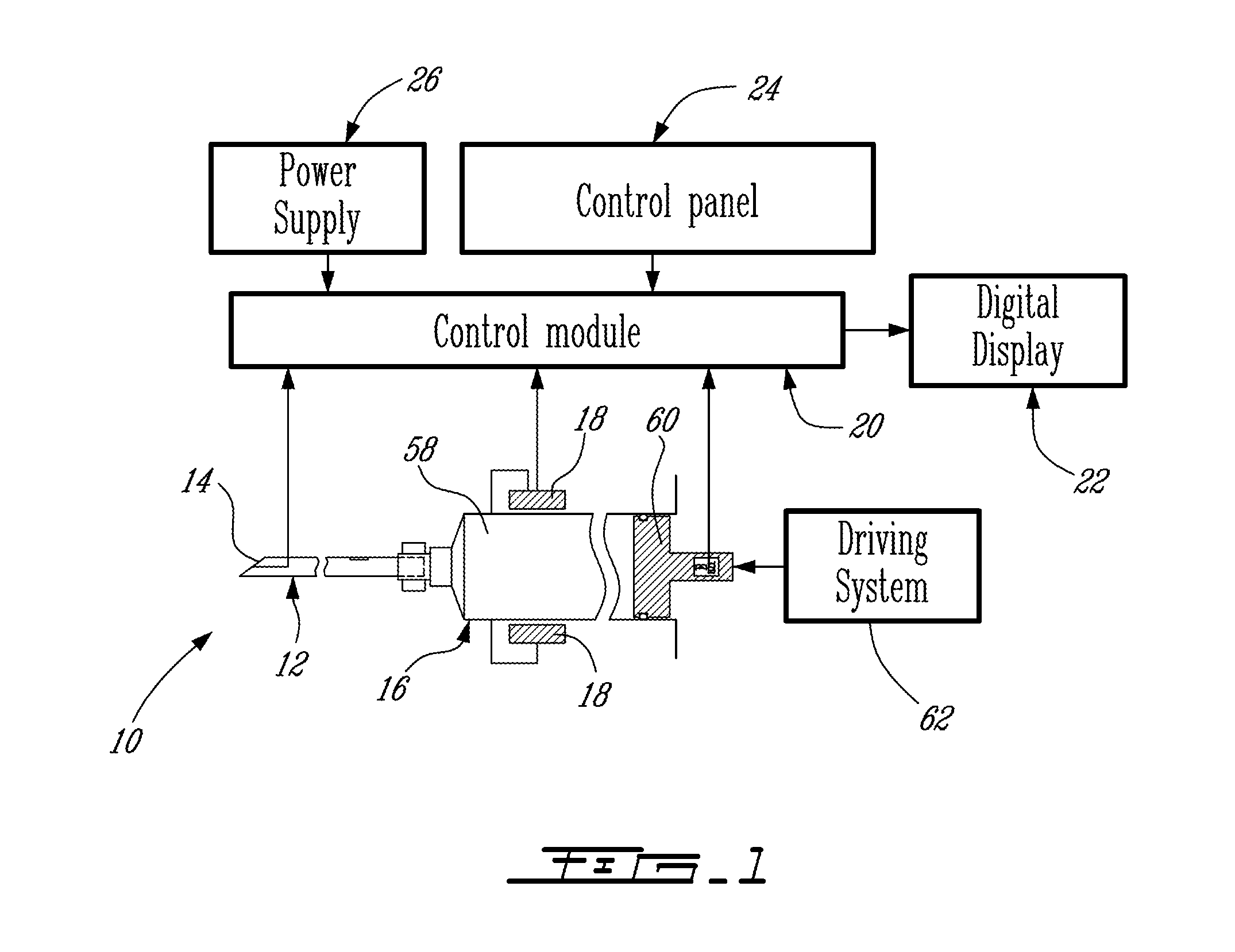
[0057]Referring generally to FIG. 1, a cement delivery system according to a particular embodiment of the present invention is generally and schematically shown at 10. The system 10 generally comprises a cannula 12 which may include pressure sensors 14 to measure the intravertebral pressure, an assisted cement delivery device 16 delivering cement through the cannula 12 and including miniature viscosity sensors 18 to monitor a viscosity of the cement, a controller or control module 20, such as for example provided in an electronic circuit board including a microprocessor, for controlling or operating the cement delivery device 16, a digital display unit 22 for displaying sensor data during the procedure, a control or regulation panel 24 for receiving instructions from a user, and a power supply 26 providing power to the system 10.

[0058]The different elements of the cement delivery system 10 are separately described in more detail in the following.

Cannulae 12

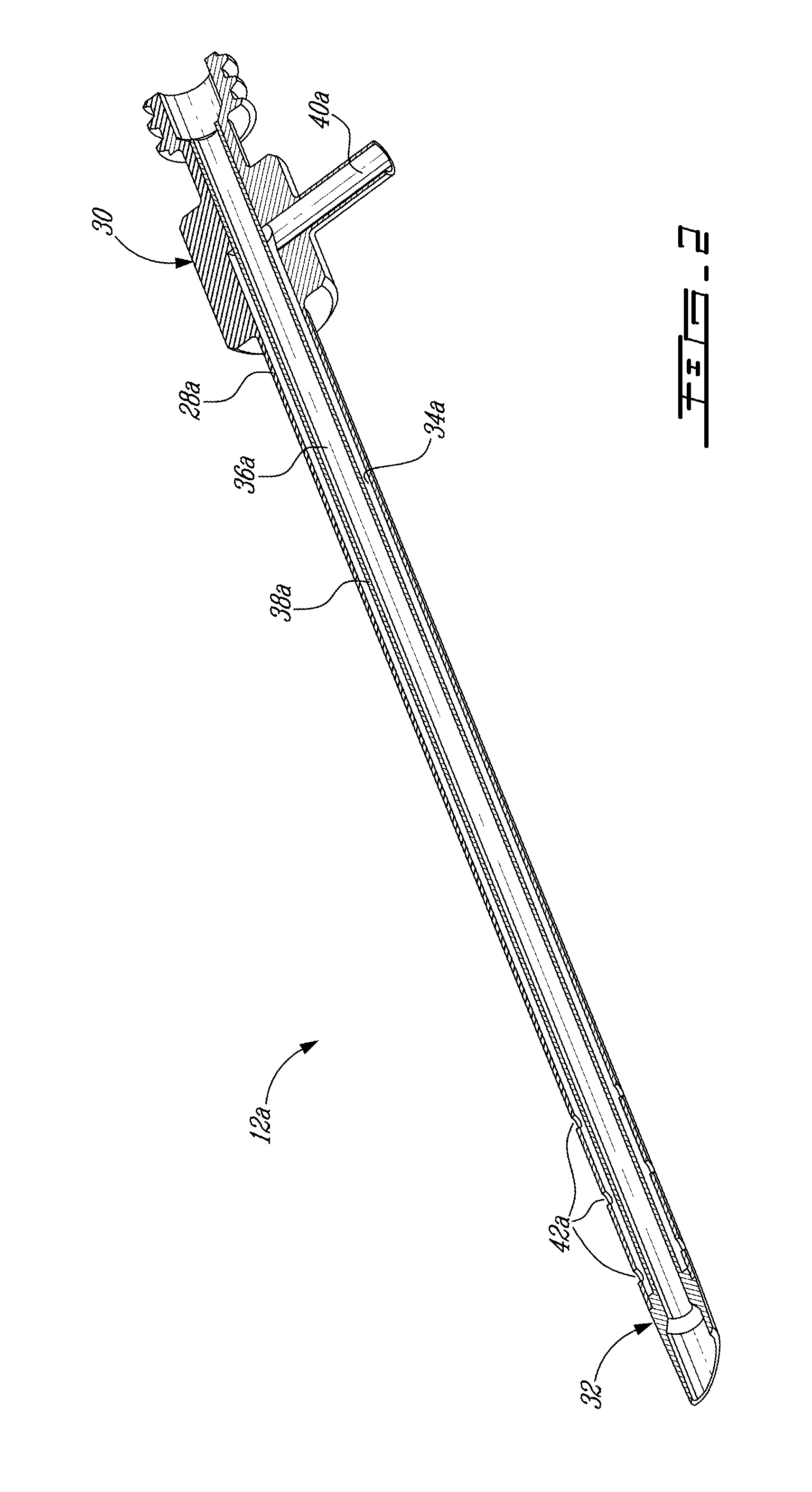
[0059]The cannula 12 in FI...


PUM

PropertyMeasurementUnit
Grain sizeaaaaaaaaaa
Storage modulusaaaaaaaaaa

Abstract

A method of harvesting bone marrow, including percutaneously introducing a multi-lumen cannula into a cancellous bone, applying suction through a first passage defined in a first lumen of the cannula, injecting a thick flowable material into the bone from a second passage in a second lumen of the cannula, extruding the thick flowable material through a distal end of the cannula into the cancellous bone in order to displace the bone marrow and other bone fluids, the suction applied through the first passage providing a hydraulic force guiding the displaced bone marrow and collecting the displaced bone marrow for a therapeutic or diagnostic purpose. A thick flowable material for use in harvesting bone marrow in the cancellous portion of a bone and a method for percutaneously preparing a bone with a multi-lumen cannula and an inflatable device are also discussed.

Description

CROSS-REFERENCE TO RELATED APPLICATIONS[0001]This application is a continuation-in-part of U.S. application Ser. No. 13 / 790,378 filed Mar. 8, 2013, which is a continuation of U.S. application Ser. No. 12 / 246,798 filed Jul. 10, 2008, which is a continuation-in-part of PCT Patent Application No. PCT / CA2007 / 000579 filed Apr. 5, 2007, which claims priority from U.S. Provisional Patent Application No. 60 / 789,891 filed Apr. 7, 2006, all of which are incorporated by reference herein.FIELD OF THE INVENTION[0002]The present invention relates to an apparatus for performing bone augmentation procedures, and more particularly to a cement delivery system for such procedures and to a method for the use of such a system.BACKGROUND ART[0003]A number of different types of bone cement injection procedures are routinely practiced, among which is vertebroplasty.[0004]Unfortunately, the pressure required to inject cement can easily reach values beyond human physical limit. A number of pressure-controlle...

Claims


Application Information

Patent Timeline
IPC IPC(8): A61B17/88A61B10/02A61L24/08
CPCA61B17/8811A61B10/025A61B17/8816A61M2202/10A61L24/08A61B2010/0258A61M1/008A61B17/8822A61B5/03A61M5/20A61M5/32A61M5/3286A61M5/329A61M5/347A61M5/484A61M5/488A61B2017/00685A61B2017/8844A61F2230/0069A61F2230/0071A61B2090/032A61B2090/064A61B90/50A61B34/10A61B90/37A61B5/150015A61B5/150099A61B5/150213A61B5/150389A61B5/150503A61M5/1456A61M5/14566A61B2218/007A61B17/8805A61B17/8819A61B18/06A61B2018/00565A61B2018/00577A61B2218/002A61N5/1007A61N2005/1021A61M5/142A61B2090/3916A61B2090/3966
Inventor BAROUD, GAMAL
Owner BAROUD GAMAL
Learn More