Textile sleeve with adhesive fixation layer and methods of construction and use thereof

a technology of textile sleeves and fixing layers, applied in protective fabrics, cable installations in underground tubes, knitting, etc., can solve problems such as ineffective application, process delay, and inability to apply correctly, and achieve the effect of preventing inadvertent damage or ineffective application

Active Publication Date: 2016-03-24
FEDERAL MOGUL POWERTAIN LLC
View PDF8 Cites 6 Cited by
  • Summary
  • Abstract
  • Description
  • Claims
  • Application Information

AI Technical Summary

Benefits of technology

[0017]In accordance with another aspect of the invention, a method of bonding at least a portion of a textile sleeve to at least one of itself and an elongate member extending through a cavity of the sleeve, wherein the textile sleeve has a wall of interlaced yarn forming an innermost and outermost surface extending between opposite open ends and further has a dry adhesive coating on at least a portion of at least one of the innermost and outermost surface is provided. The method includes wetting the dry adhesive coating with water; and pressing the wetted adhesive coating into abutment with at least one of the innermost surface, the outermost surface and the elongate member and causing the adhesive coating to bond to the surface that it abuts.

Problems solved by technology

The use of tape to secure the sleeve in place has various drawbacks, as it is costly from a material and labor standpoint, and it can also prove unsightly if not applied correctly.
Further, the externally applied tape must be readily available during installation of the sleeve, otherwise the assembly process can be delayed, and further yet, the tape can become inadvertently damaged or ineffectively applied during assembly, such as by being inadvertently folded on itself or contaminated via dirty surroundings or hands during application, thus, adversely affecting the ability of the tape to reliably fix the sleeve as intended.
The application of separately applied glue during assembly is also costly from a material and labor standpoint, and further requires being readily available during assembly of the sleeve, and can further add cost as a result of the need to provide drying time for the glue.
In addition, glue lacks strength is elevated temperatures, and can prove messy in application, thereby leading to further cost associated with damage, repair and the necessary clean-up thereof.

Method used


Image

  • Textile sleeve with adhesive fixation layer and methods of construction and use thereof
  • Textile sleeve with adhesive fixation layer and methods of construction and use thereof
  • Textile sleeve with adhesive fixation layer and methods of construction and use thereof

Examples


Embodiment Construction

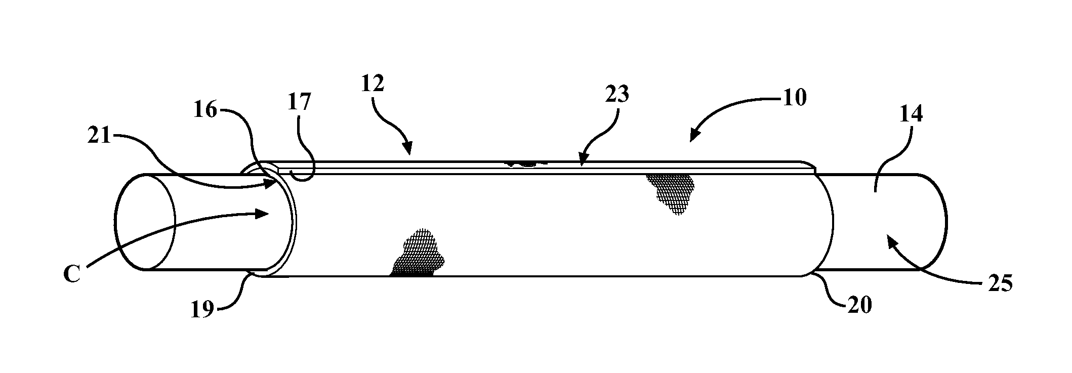
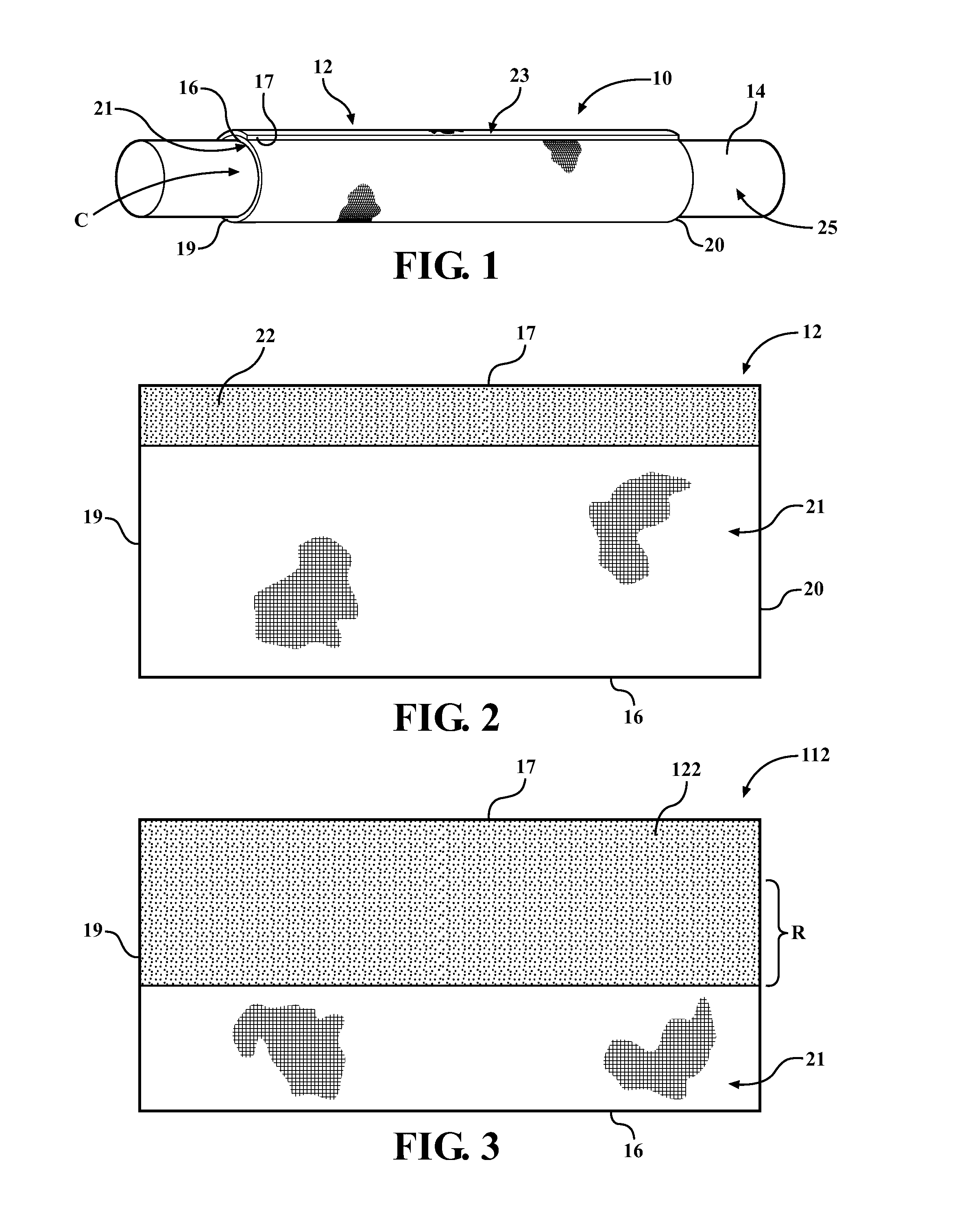
[0033]Referring in more detail to the drawings, FIG. 1 illustrates a textile sleeve constructed in accordance with one aspect of the invention, shown as a wrappable sleeve, by way of example and without limitation, and referred to hereafter as sleeve 10. The sleeve 10 has a wrappable wall 12, such as a self-wrapping elongate wall that automatically curls into its wrapped configuration absent some externally applied force, for routing and protecting elongate members 14, such as a cable, wire harness, or tube, by way of example and without limitation. The elongate wall 12 has opposite inner and outer free edges 16, 17 extending generally parallel to a central, longitudinal axis 18 between opposite open ends 19, 20, wherein the edges 16, 17 can be biased into overlapping relation with one another in “cigarette wrapped” fashion to fully enclose the elongate member(s) 14 within a central cavity C of the sleeve 10. The wall 12 has an innermost face or surface, also referred to as inner su...


PUM

PropertyMeasurementUnit
adhesiveaaaaaaaaaa
wettingaaaaaaaaaa
timeaaaaaaaaaa

Abstract

A protective textile sleeve for providing protection to an elongate member contained therein; a method of construction thereof, and a method of bonding at least a portion of the sleeve to at least one of itself and an elongate member extending through a cavity thereof is provided. The sleeve has a wall of interlaced yarn, with the wall having an outermost surface and an innermost surface. The innermost surface is configured to bound a cavity extending between opposite open ends. The sleeve further includes an adhesive coating bonded to at least a portion of at least one of the outermost and innermost surfaces. The adhesive coating has a first, dried non-adhesive state and a second, wetted adhesive state, wherein the second adhesive state is activated via application of a water-based liquid thereto.

Description

CROSS-REFERENCE TO RELATED APPLICATION[0001]This application claims the benefit of U.S. Provisional Application Ser. No. 62 / 054,797, filed Sep. 24, 2014, which is incorporated herein by reference in its entirety.BACKGROUND OF THE INVENTION[0002]1. Technical Field[0003]This invention relates generally to protective textile sleeves for providing protection to elongate members contained therein, and more particularly to protective textile sleeves having an adhesive mechanism for fixing a portion of the sleeve to itself and / or to an elongate member extending therethrough.[0004]2. Related Art[0005]Protective textile sleeves for providing protection to elongate members extending therethrough are known. Typically, the protective sleeves are formed having one of a tubular wall having a circumferentially continuous wall, or a wrappable wall having opposite lengthwise extending edges configured to be wrapped into overlapping relation with one another. Depending on the type of aforementioned w...

Claims


Application Information

Patent Timeline
Patent Type & Authority Applications(United States)
IPC IPC(8): C09J7/04D04B21/20D04B1/22D03D1/00D03D3/02C09J7/21C09J7/32
CPCC09J7/042D03D1/0035D03D3/02D04B1/225D04B21/205D10B2331/042D10B2331/301C09J2201/16C09J2201/614H02G3/0406H02G3/0481H02G9/04H02G9/06C09J7/21C09J7/32C09J2301/306C09J2301/16
Inventor FUKUYAMA, SHOZO
Owner FEDERAL MOGUL POWERTAIN LLC
Why Eureka
Try Eureka