Circuit-loaded conformal metasurface cloak

a conformal metasurface and circuit-loaded technology, applied in the direction of antennas, electrical equipment, etc., can solve the problem of similar bandwidth limitations

Inactive Publication Date: 2016-03-24
BOARD OF RGT THE UNIV OF TEXAS SYST
View PDF0 Cites 23 Cited by
  • Summary
  • Abstract
  • Description
  • Claims
  • Application Information

AI Technical Summary

Problems solved by technology

Still, similar bandwidth limitations apply to the current implementation of mantle cloaks, and they are fundamentally related to the passivity of these designs.

Method used


Image

  • Circuit-loaded conformal metasurface cloak
  • Circuit-loaded conformal metasurface cloak
  • Circuit-loaded conformal metasurface cloak

Examples


Embodiment Construction

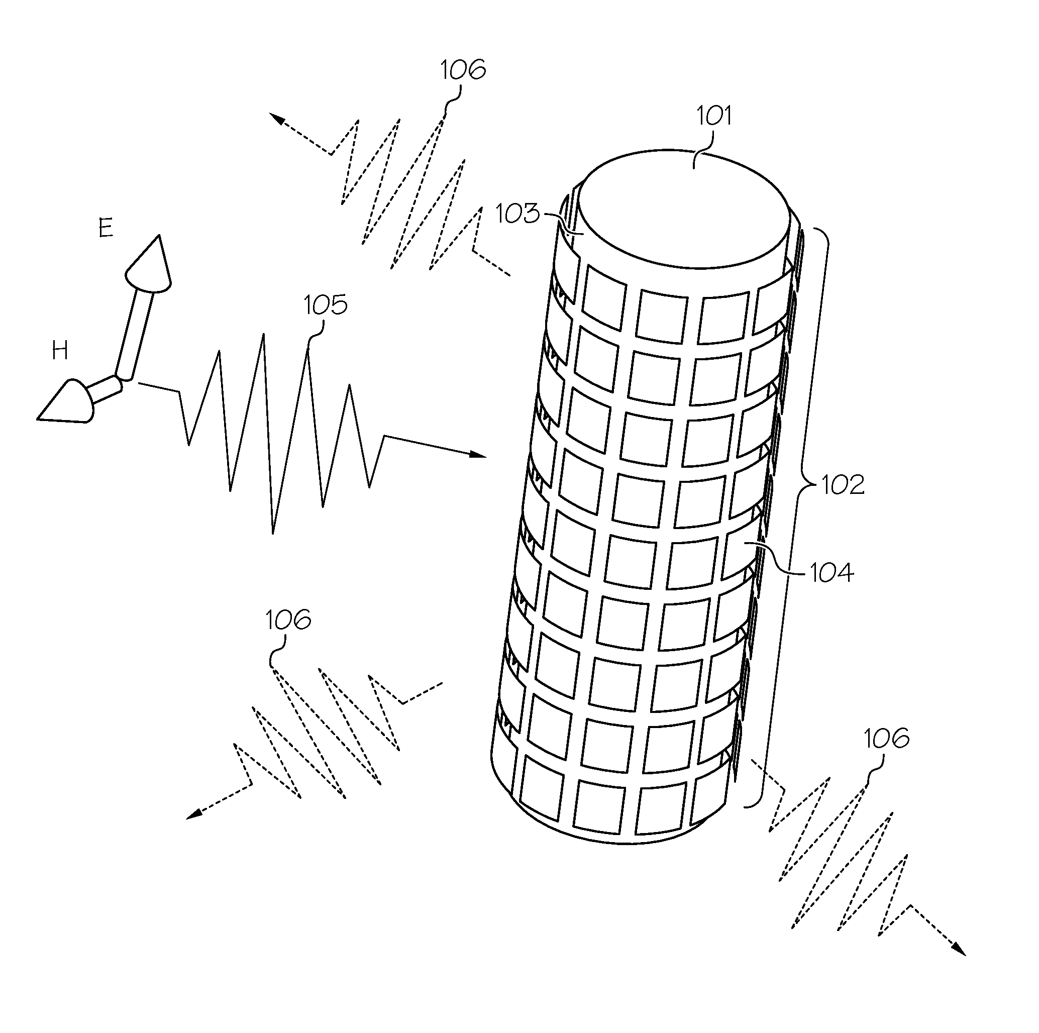
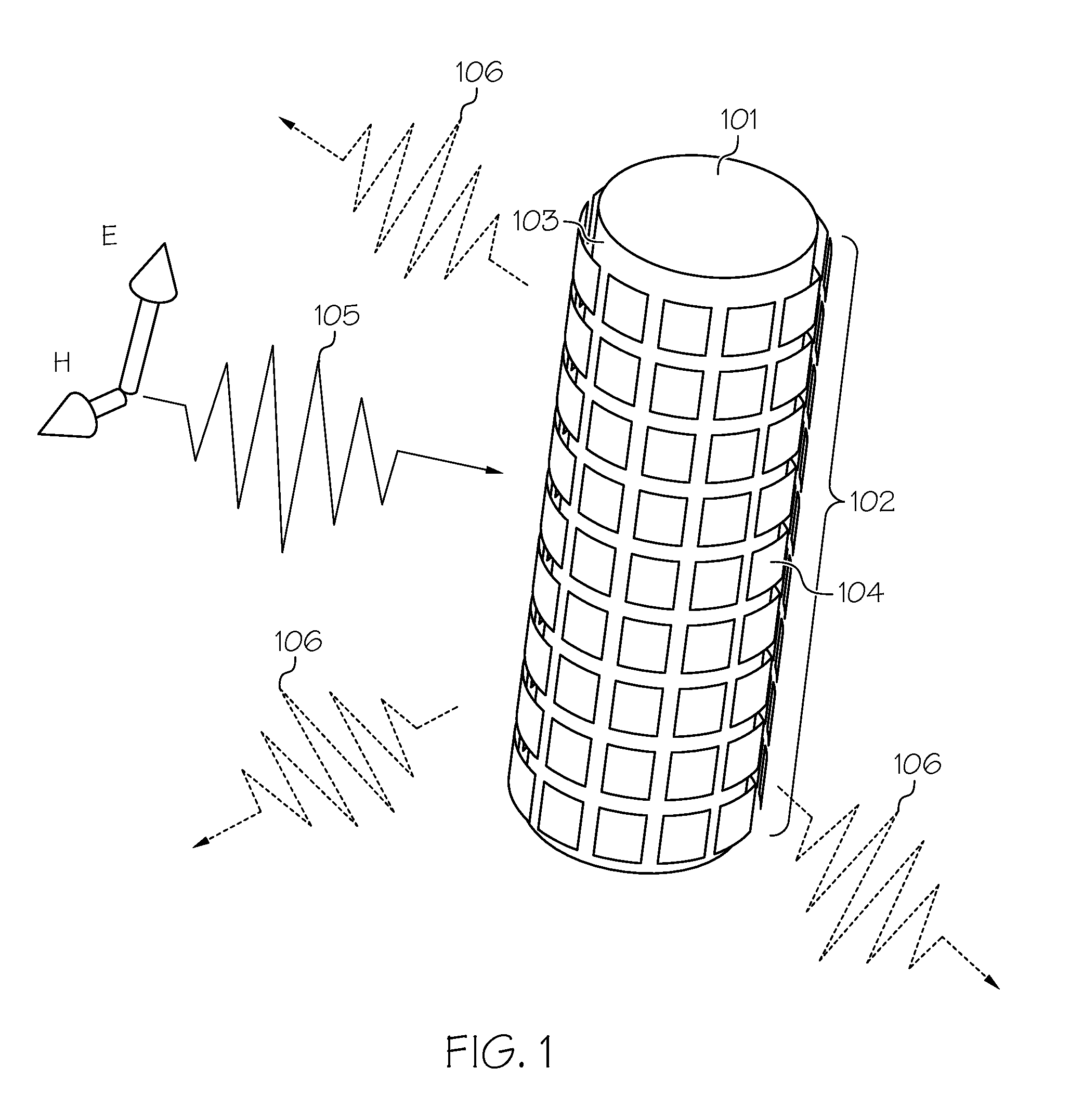
[0021]As stated in the Background section, in “mantle cloaking,” a suitably designed metasurface supports current distributions radiating “anti-phase” fields that cancel the scattering from the covered object. Mantle cloaks can be readily realized at microwaves by patterning a metallic surface around the object of interest, and various structural designs have been proposed in the context of metasurfaces and frequency-selective surfaces (FSS). It has been recently shown that even a one-atom-thick graphene monolayer may achieve scattering suppression at THz frequencies. The ultrathin profile of mantle cloaks makes their practical realization easier than bulk metamaterial cloaks, and it is also usually associated with a moderate bandwidth improvement compared with the other cloaking techniques based on bulk metamaterials. Still, similar bandwidth limitations apply to the current implementation of mantle cloaks, and they are fundamentally related to the passivity of these designs. Achie...


PUM


Abstract

An electromagnetic invisibility cloaking device with a broadened cloaking bandwidth and/or a tunable frequency of operation. The cloaking device includes an object (e.g., antenna) and a metasurface (301) that conforms to the surface design of the object. The metasurface includes an array of metal cells (302A, . . . , 302Y), where each of the metal cells includes a circuit element (304) (e.g., active, passive, negative impedance converter element). The array of metal cells may be represented as an array of metal square patches, a mesh grid, horizontal or vertical conductive strips, or any arbitrary combination of unit cell patterns, where each opening, or a subset of them, in such an array includes an embedded circuit element. By incorporating the circuit elements in the conformal metasurface, the cloaking bandwidth is broadened and the frequency of operation is actively controlled and tuned.

Description

CROSS REFERENCE TO RELATED APPLICATIONS[0001]This application claims priority to U.S. Provisional Patent Application Ser. No. 61 / 820,224, “Broadening Mantle Cloak Using Non-Foster Metamaterial Surfaces,” filed on May 7, 2013, which is incorporated by reference herein in its entirety.GOVERNMENT INTERESTS[0002]The U.S. Government has certain rights in this invention pursuant to the terms of the National Science Foundation Grant No. ECCS-0953311; Air Force Office of Scientific Research Grant No. FA9550-11-1-0009; and Defense Threat Reduction Agency Young Investigator Program Grant No. HDTRA1-12-1-0022.TECHNICAL FIELD[0003]The present invention relates generally to electromagnetic invisibility cloaks, and more particularly to broadening the cloaking bandwidth by incorporating circuit elements in a conformal metasurface cloak.BACKGROUND[0004]In recent years, there has been an increased interest in the study of electromagnetic invisibility cloaks due to their promising applications in cam...

Claims


Application Information

Patent Timeline
Patent Type & Authority Applications(United States)
IPC IPC(8): H01Q17/00
CPCH01Q17/008H01Q17/007H01Q15/148
Inventor ALU, ANDREASORIC, JASONCHEN, PAI-YEN
Owner BOARD OF RGT THE UNIV OF TEXAS SYST
Why Eureka
Try Eureka