
Wireless charging apparatus

a charging apparatus and wireless technology, applied in the field of wireless charging apparatus, can solve the problems of high manufacturing cost, high manufacturing cost, rf noise generation, etc., and achieve the effect of ensuring a degree of freedom in a location and wasting power

Inactive Publication Date: 2016-03-24
SAMSUNG ELECTRONICS CO LTD
View PDF12 Cites 18 Cited by
  • Summary
  • Abstract
  • Description
  • Claims
  • Application Information

AI Technical Summary

Benefits of technology

The patent text describes a wireless charging method that uses light sources and a solar cell module to generate electricity without RF noise. The method provides higher power transfer efficiency than other wireless charging methods, but requires high manufacturing costs and may generate high heat. The text also mentions that a wireless charging apparatus may use a low degree of freedom in charging or expensive components, and may require a highly conductive conductor for efficient charging. The technical effect of the patent text is to provide a more cost-effective and safe wireless charging method that reduces RF noise and provides a degree of freedom in charging location.

Problems solved by technology

However, the electromagnetic inductive charging method provides higher power transfer efficiency compared to other wireless charging methods, but requires high manufacturing costs since a low degree of freedom in charging or expensive components are used.
In addition, an eddy current generated from the electromagnetic inductive charging method causes high heat, and a highly conductive conductor is required to obtain high efficiency between a wireless power transmitter and a wireless power receiver and thus, the manufacturing costs are high and RF noise may be generated.
In addition, wireless charging through the resonant magnetic coupling method provides a high degree of the freedom in location for charging, compared to the above described electromagnetic inductive charging method, but a highly conductive conductor needs to be used to obtain high charging efficiency and thus, manufacturing costs may increase.
In addition, wireless charging through the radiated emission method may have significantly lower charging efficiency, compared to the above described two methods, and generates high-power radiation and makes noise.
In addition, the wireless charging through the energy harvesting method may provide significantly low charging power.

Method used


Image

  • Wireless charging apparatus
  • Wireless charging apparatus
  • Wireless charging apparatus

Examples


Embodiment Construction

[0036]Various embodiments of the present disclosure will now be described more fully in conjunction with the accompanying drawings. The present disclosure may have various embodiments, and modifications and changes may be made therein. Therefore, the present disclosure will be described in detail with reference to particular embodiments shown in the accompanying drawings. However, it should be understood that there is no intent to limit various embodiments of the present disclosure to the particular embodiments disclosed, but the present disclosure should be construed to cover all modifications, equivalents, and alternatives falling within the spirit and scope of the various embodiments of disclosure. In the description of the drawings, identical or similar reference numerals are used to designate identical or similar elements.

[0037]Hereinafter, the terms “include” or “may include”, which may be used in various embodiments of the present disclosure, refer to the presence of disclose...


PUM


Abstract

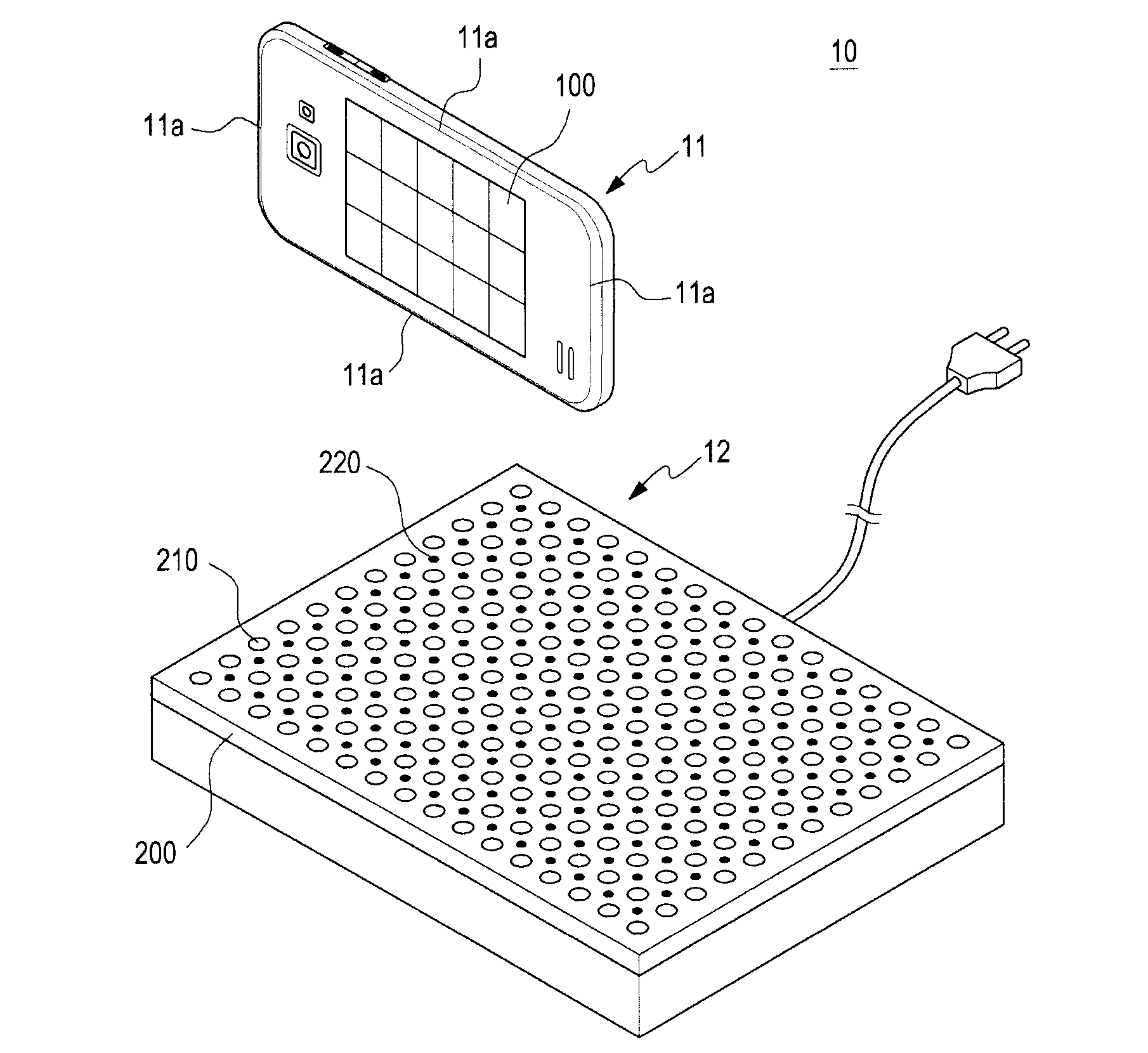
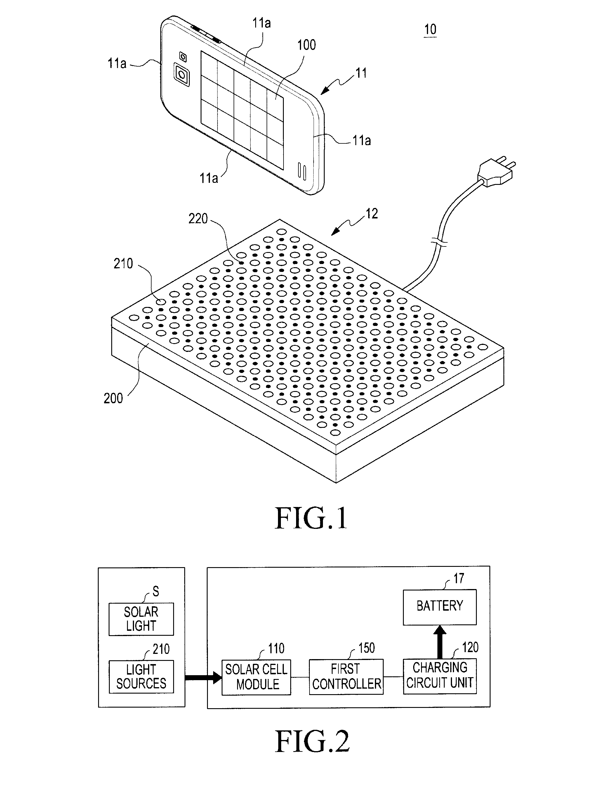
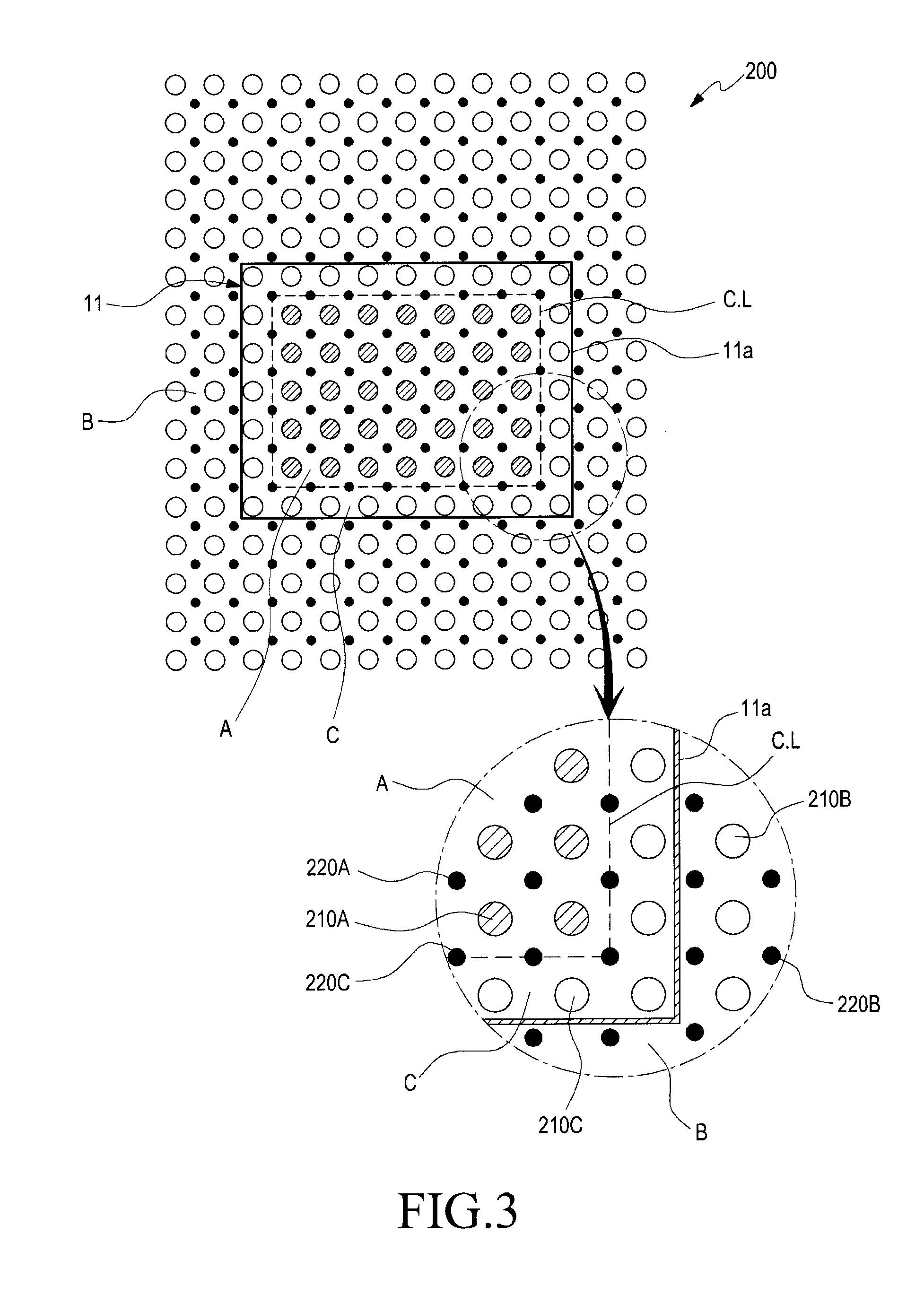
A wireless charging apparatus according to various embodiments of the present disclosure may include a wireless power transmitter that is included in a charging pad where an electronic device is placed, and may include a light source unit that provides light to a solar cell module included in the electronic device, wherein the light source unit may include a plurality of light sources that emit light outside the charging pad, and a plurality of sensors that are disposed between the light sources and close to the light sources and sense the electronic device.

Description

CLAIM OF PRIORITY[0001]This application claims the priority under 35 U.S.C. §119(a) to Korean Application Serial No. 10-2014-0126989, which was filed in the Korean Intellectual Property Office on Sep. 23, 2014, the entire contents of which are hereby incorporated by reference.BACKGROUND[0002]1. Technical Field[0003]The present disclosure generally relates to a wireless charging apparatus, and more particularly, to a wireless charging apparatus that readily disperses heat generated during wireless charging.[0004]2. Description of the Related Art[0005]Electronic devices may include a battery for supplying power to the electronic device. Various methods for charging the battery may be used. Recently, an apparatus for charging a battery through wireless charging (or contactless charging) have been proposed. Wireless charging (or contactless charging) technologies are utilized for charging a battery of an electronic device that uses a rechargeable battery. The wireless charging technolog...

Claims


Application Information

Patent Timeline
Patent Type & Authority Applications(United States)
IPC IPC(8): H02J7/02
CPCH02J7/025H02J50/90H02J50/30H02J7/0042H02J7/35Y02E70/30Y02E10/56H02J50/005H04B10/807H02J2300/24
Inventor KIM, JOON-IL
Owner SAMSUNG ELECTRONICS CO LTD
Learn More