System and Method for Broadband Signal Disambiguation based on Sub-Sampled Analog Optical Links Employing Sample Rate Modulation

a broadband signal and sample rate modulation technology, applied in the field of subsampled analog links, can solve the problems of dramatic increase in the bandwidth over which we disambiguate, and achieve the effect of coarse disambiguation and increased bandwidth

Inactive Publication Date: 2016-03-24
THE UNITED STATES OF AMERICA AS REPRESENTED BY THE SECRETARY OF THE NAVY
View PDF11 Cites 11 Cited by
  • Summary
  • Abstract
  • Description
  • Claims
  • Application Information

AI Technical Summary

Benefits of technology

[0008]There are two primary advantages to our technique. First, the use of optical sampling dramatically increases the bandwidth over which our disambiguation technique may be applied—while the technique itself may also be applied to all-electronic ADC architectures, the RF bandwidth of these devices is typically only twice the sample rate. Here, we may approach an RF bandwidth of 100 GHz or more as determined by the optical modulator. The second advantage is that coarse disambiguation is achieved in a single acquisition. Other techniques, for example using multiple sample frequencies, require at least two acquisitions (either serial or parallel in time) which may be intractable in some applications.

Problems solved by technology

First, the use of optical sampling dramatically increases the bandwidth over which our disambiguation technique may be applied—while the technique itself may also be applied to all-electronic ADC architectures, the RF bandwidth of these devices is typically only twice the sample rate.

Method used


Image

  • System and Method for Broadband Signal Disambiguation based on Sub-Sampled Analog Optical Links Employing Sample Rate Modulation
  • System and Method for Broadband Signal Disambiguation based on Sub-Sampled Analog Optical Links Employing Sample Rate Modulation
  • System and Method for Broadband Signal Disambiguation based on Sub-Sampled Analog Optical Links Employing Sample Rate Modulation

Examples


Embodiment Construction

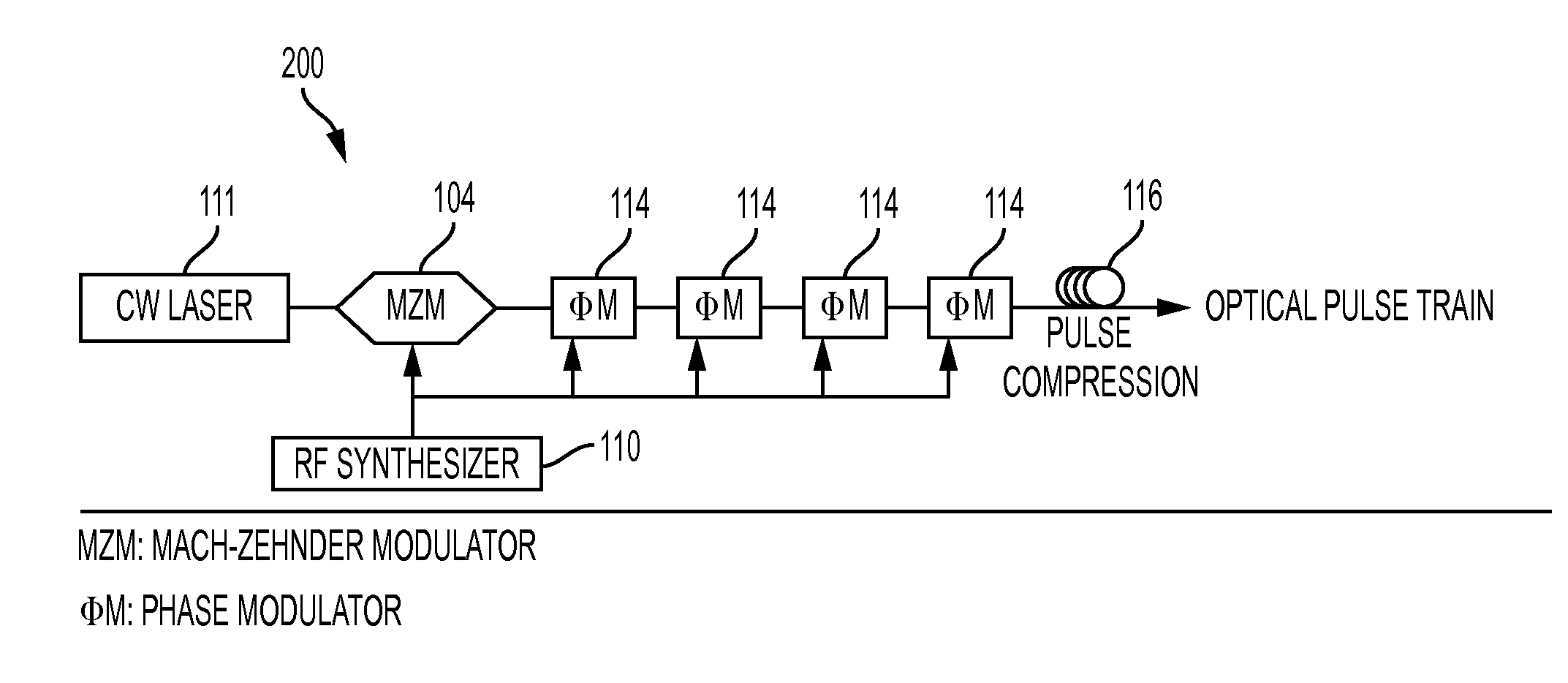
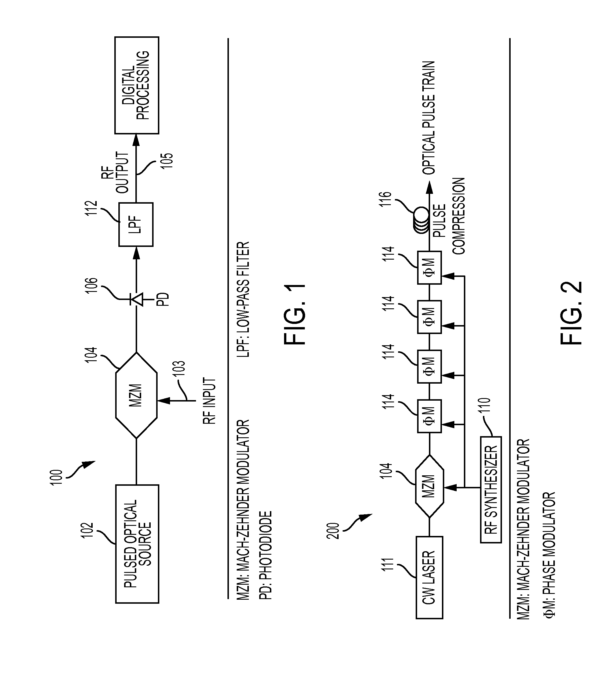
[0015]The basic architecture for a sampled analog optical link 100 is shown in FIG. 1. The pulse train from a pulsed optical source 102 optically samples the incoming RF signal 103 via a Mach-Zehnder intensity modulator 104. The output RF signal 105 is recovered by direct detection of the modulated optical pulse train with a photodiode 106. From sampling theory it is well-known that, when the frequency of the RF input (ωin / 2π) exceeds one-half of the optical sampling rate (ωrep / 2π), the RF output will be aliased to a frequency of {tilde over (ω)}=ωrep−(ωin mod ωrep)

[0016]which may also be written as {tilde over (ω)}=nωrep−ωin where n represents the index of the alias band where the original signal resides. Clearly, when no steps are taken to prevent aliasing there may be substantial ambiguity in the detected RF output of the link. In many applications, the input frequency range is limited by placing an appropriate anti-aliasing filter at the link input, thereby restricting the input...


PUM


Abstract

A system for measuring an RF input signal frequency includes a sampling optical pulse train with a frequency-dithered repetition-rate, and a sub-sampled analog link coupled to the optical pulse train whereby the RF input signal frequency is determined. This frequency dither imparts well-characterized modulation sidebands onto the input RF signal to be measured. By measuring the amplitude of these sidebands relative to the incoming aliased signal amplitude the frequency of the original signal is readily determined. The use of optical sampling dramatically increases the bandwidth over which the disambiguation technique is applied, and coarse disambiguation is achieved in a single acquisition.

Description

CROSS-REFERENCE TO RELATED APPLICATIONS[0001]This application claims the benefit of U.S. Provisional Application 62 / 054,131 filed on Sep. 23, 2014, and incorporated herein by reference.FIELD OF THE INVENTION[0002]The invention is directed to a sub-sampled analog link, and more particularly to one which uses a sampling optical pulse train with a frequency-dithered repetition rate to determine an RF signal frequency.BACKGROUND OF THE INVENTION[0003]With increasing radio-frequency (RF) spectral occupancy it is becoming increasingly important for electronic support measures (ESM) systems to monitor the radio-frequency spectrum from well below 1 GHz to nearly 100 GHz in real time. Photonic architectures for signal down-conversion (subsampling) and disambiguation are enabling technologies for real-time wideband signal monitoring which could provide lower size-weight-power-cost (SWaP-C) and reduced latency in next-generation military ESM and civilian applications.[0004]From sampling theory...

Claims


Application Information

Patent Timeline
Patent Type & Authority Applications(United States)
IPC IPC(8): H04B10/079H04B10/11
CPCH04B10/11H04B10/079H04B10/00H04B2210/006
Inventor MCKINNEY, JASON, D.HARMON, SHARON, R.
Owner THE UNITED STATES OF AMERICA AS REPRESENTED BY THE SECRETARY OF THE NAVY
Why Eureka
Try Eureka