
Unmanned aerial vehicle for antenna radiation characterization

a technology of unmanned aerial vehicles and antenna radiation, applied in the field of antenna radiation pattern characterization, can solve the problems of only generating a two-dimensional approximation of the true three-dimensional radiation pattern, and not capturing the effect of its surroundings on its actual performan

Inactive Publication Date: 2016-03-24
KING FAHD UNIVERSITY OF PETROLEUM AND MINERALS
View PDF5 Cites 305 Cited by
  • Summary
  • Abstract
  • Description
  • Claims
  • Application Information

AI Technical Summary

Benefits of technology

The present invention is about an unmanned aerial vehicle that can be used to analyze the radiation pattern of an antenna. The vehicle has a propulsion system and a transceiver and can be controlled from a base station to position itself near the antenna. It also has a signal strength antenna that receives the antenna signal and sends it back to the base station in real-time. This signal represents the strength of the antenna signal at different locations in three dimensions, providing a detailed analysis of the antenna's radiation pattern. The technical effect of this invention is its ability to accurately analyze the radiation pattern of an antenna in real-time, which can be useful in various applications such as wireless communication.

Problems solved by technology

However, such mobile devices are typically carried by ground vehicles or the like, thus generating only a two-dimensional approximation of the true three-dimensional radiation pattern.
However, such approaches generally require bringing the antenna under test to a testing facility and typically do not capture the effect of its surroundings on its actual performance when placed in the actual location or site where it can be surrounded by structures, buildings, trees, etc., for example.
Although unmanned aerial vehicles, such as unmanned drones and the like, are known, such vehicles typically only have transceivers adapted solely for navigational purposes.

Method used


Image

  • Unmanned aerial vehicle for antenna radiation characterization
  • Unmanned aerial vehicle for antenna radiation characterization
  • Unmanned aerial vehicle for antenna radiation characterization

Examples


Embodiment Construction

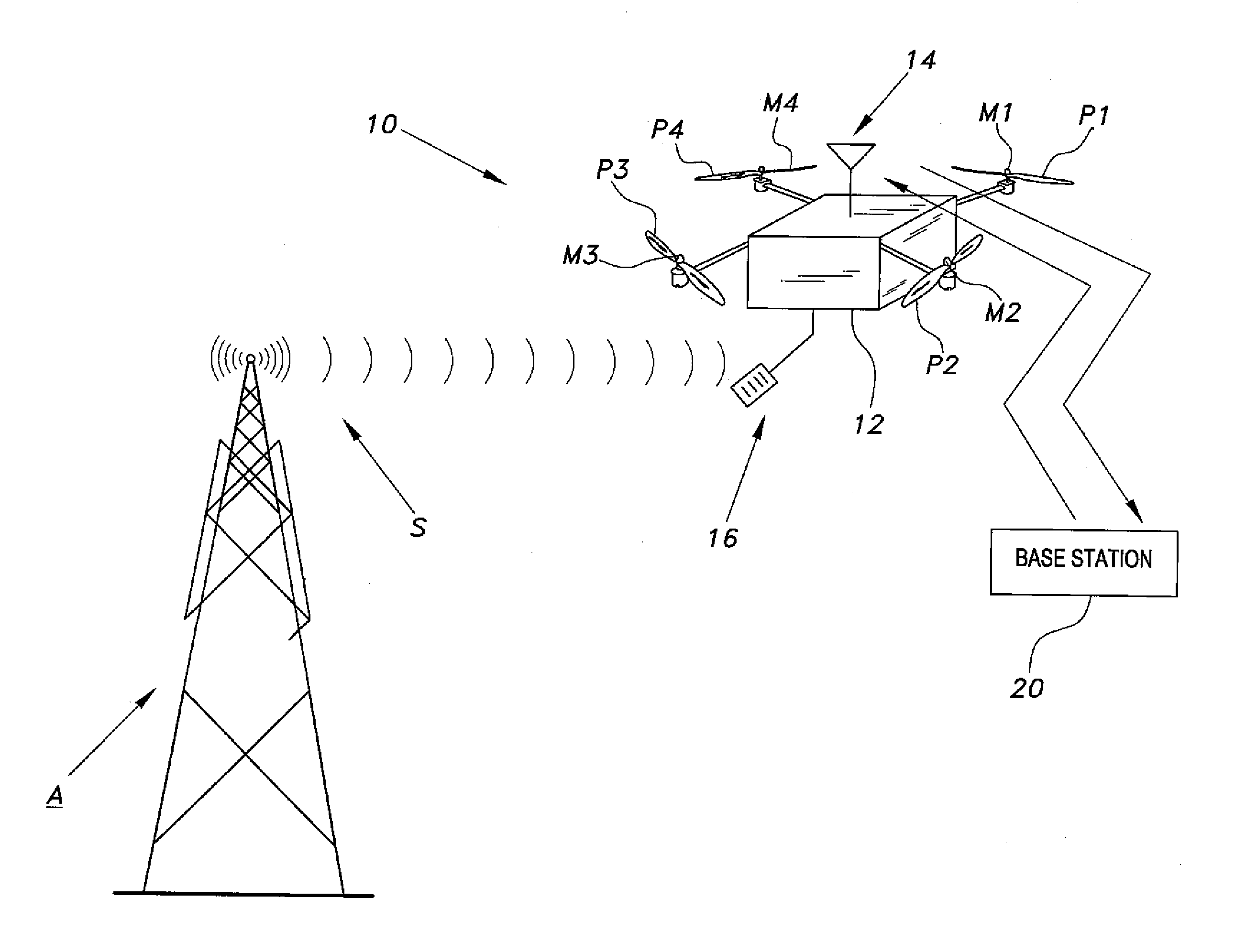
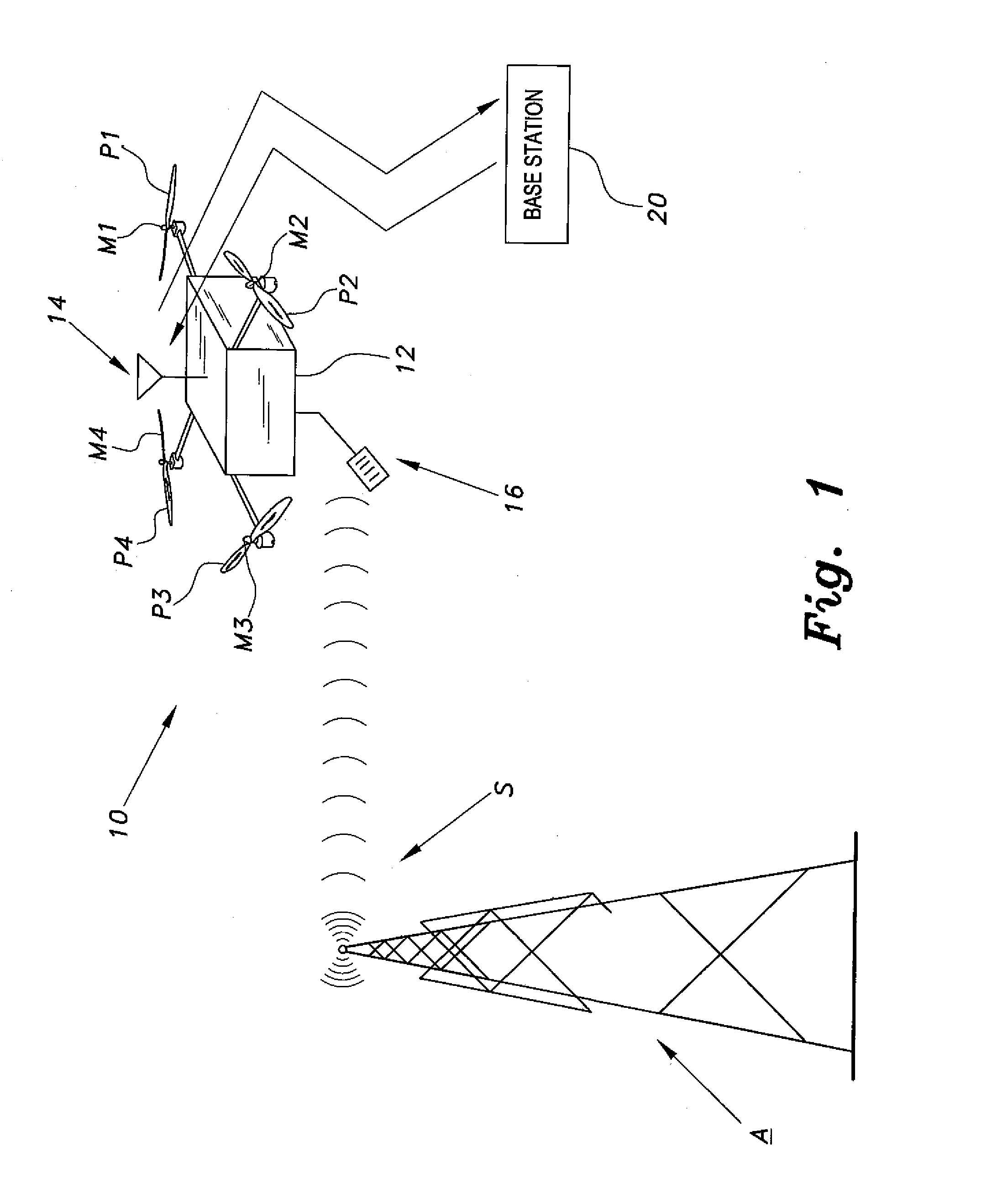
[0014]The unmanned aerial vehicle (UAV) for antenna radiation characterization 10 (“UAV 10”) is an unmanned aerial vehicle adapted for sensing and mapping received signal strength of a signal transmitted from an antenna for three-dimensional characterization of the antenna signal, such as can use a radio frequency (RF) type system. Embodiments of the UAV for antenna radiation characterization provide an antenna radiation pattern measurement system that utilizes a UAV, such as the UAV 10, to fly in the area around a stationary antenna and collect the data to determine the radiation characteristics and a shape of the stationary antenna. As shown in FIG. 1, the unmanned aerial vehicle for antenna radiation characterization 10 is a conventional unmanned aerial vehicle having a transceiver antenna 14, for communicating with a base station 20, and a signal strength antenna 16 for sensing and receiving a signal S transmitted from antenna A.

[0015]In FIG. 1, the unmanned aerial vehicle for a...


PUM


Abstract

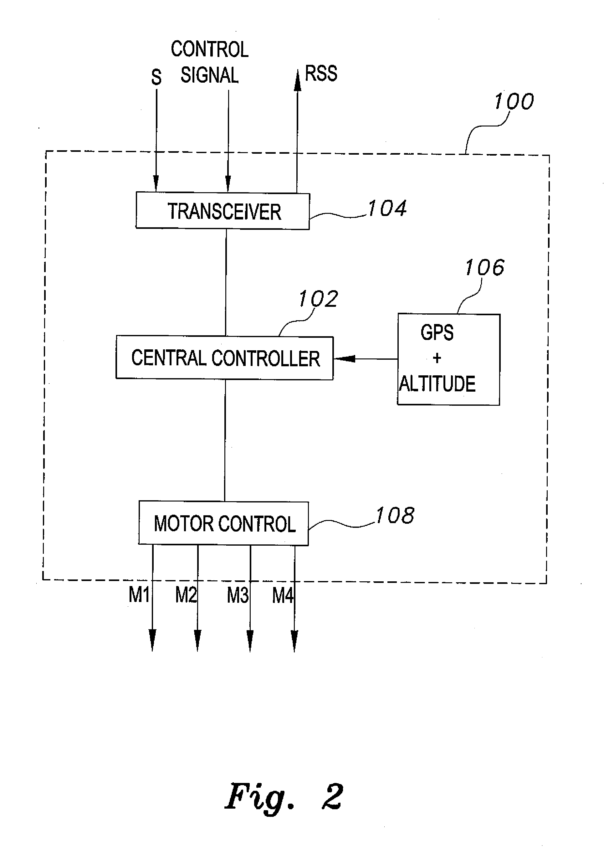
The unmanned aerial vehicle for antenna radiation characterization is an unmanned aerial vehicle having a propulsion system and a transceiver. Control signals are transmitted from a base station to position the unmanned aerial vehicle adjacent an antenna of interest. The unmanned aerial vehicle for antenna radiation characterization further includes a signal strength antenna for receiving an antenna signal generated by the antenna of interest for calculating or determining the received signal strength of the antenna signal. A received signal strength signal is then transmitted back to the base station, in real time. The received signal strength signal is representative of a set of received signal strengths of the antenna signal corresponding to a set of three-dimensional measurement coordinates such that the received signal strength signal represents a three-dimensional radiation pattern associated with the antenna of interest.

Description

BACKGROUND OF THE INVENTION[0001]1. Field of the Invention[0002]The present invention relates to characterization of antenna radiation patterns, and particularly to an unmanned aerial vehicle for antenna radiation characterization.[0003]2. Description of the Related Art[0004]Characterization of antenna radiation is used to develop radiation patterns of transmitted signals from an antenna, or antenna array, of interest. Analyses of these radiation patterns are used to show actual radiation performances of antennas after they are placed in their final fixed positions, such as tower antennas, antennas mounted on the sides of buildings, or within buildings, or the like. Typically, such patterns are developed by measuring received signal strength about the antenna using a mobile device. However, such mobile devices are typically carried by ground vehicles or the like, thus generating only a two-dimensional approximation of the true three-dimensional radiation pattern.[0005]Also, characte...

Claims


Application Information

Patent Timeline
IPC IPC(8): H04W24/08B64C39/02G01R29/10
CPCH04W24/08B64C2201/122B64C39/024G01R29/10B64U10/14B64U2101/23B64U2101/20
Inventor SHARAWI, MOHAMMAD, S.
Owner KING FAHD UNIVERSITY OF PETROLEUM AND MINERALS
Learn More