Engine system

a technology for electric power generators and engines, which is applied to power operated starters, machines/engines, and engine starters. it can solve the problems of large wasted large occupied space, and large occupied space in the device, so as to facilitate maintenance work

Active Publication Date: 2016-03-31
YANMAR POWER TECHNOLOGY CO LTD
View PDF2 Cites 9 Cited by
  • Summary
  • Abstract
  • Description
  • Claims
  • Application Information

AI Technical Summary

Benefits of technology

[0015]The detachable bottom compartment inspection window, provided in the external wall panel below the battery unit, can be removed to perform some maintenance work without having to remove, for example, the external wall panel or the battery unit. That facilitates the maintenance work.

Problems solved by technology

However, inside the package for a standard device in which no automatic startup device is installed, an empty space is left unused that was set aside to accommodate an automatic startup device for the power failure response enabled device.
In addition, the built-in battery for the automatic startup device is bulky.
The conventional example standard device therefore disadvantageously contains large wasted space in the package.

Method used


Image

  • Engine system
  • Engine system
  • Engine system

Examples


Embodiment Construction

[0024]The following will describe embodiments of the present invention in reference to drawings.

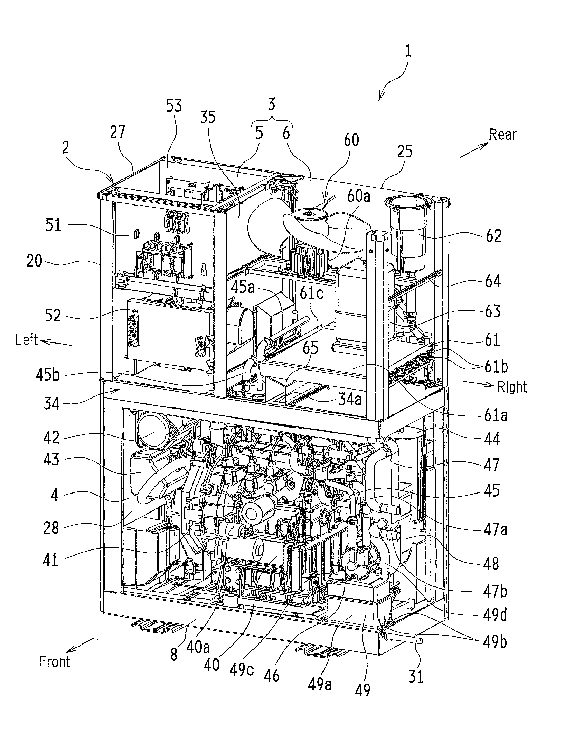
[0025]The present embodiment is an application of an energy system in accordance with the present invention to a cogeneration device 1. The cogeneration device 1 is a system that connects both an external commercial power supply from a commercial electric power system and an electric power supply from an electric power generator (via an inverter) to an electric power supply system for an electric power consuming device (load), to meet the demand for electric power by the load and that also recovers waste heat generated in power generation for later use.

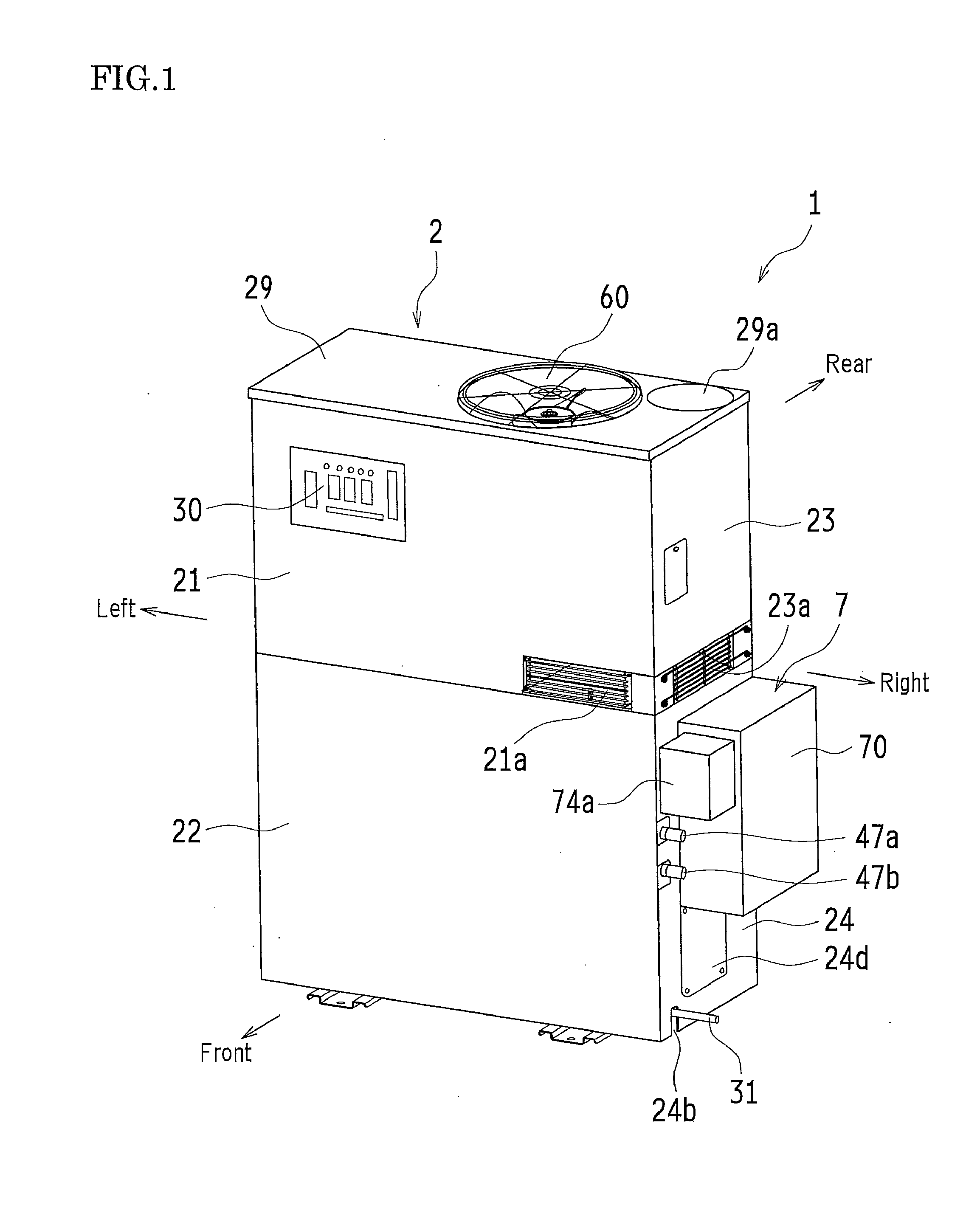
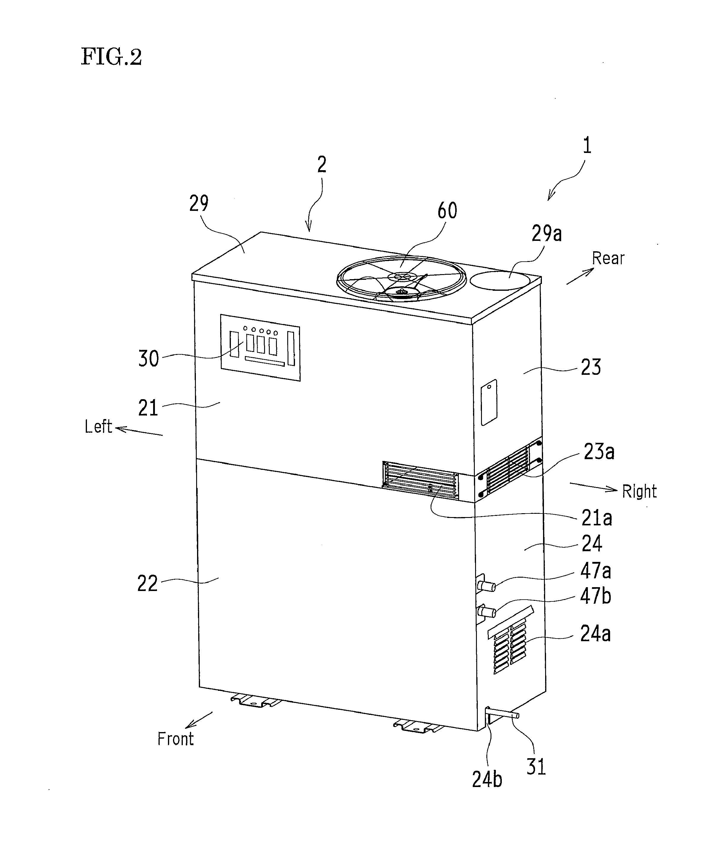
[0026]FIGS. 1 and 2 are oblique views of the cogeneration device 1 as viewed from the front. FIG. 1 shows a power failure response enabled device that automatically starts up in case of a power failure of the commercial electric power system to start electric power generation. FIG. 2 shows a standard device that does not automatically start...


PUM


Abstract

A radiator chamber is provided in a top compartment of a package, whereas an engine is provided in a bottom compartment. Outside the package, a battery unit is attached to an external wall panel (e.g., lower panel) of the bottom compartment. The battery unit includes a dedicated unit ventilation fan and a unit ventilating section that introduces outside air into an enclosure of the battery unit. The enclosure has a lower portion thereof divided to accommodate a package ventilating section that ventilates the bottom compartment of the package. There is provided a detachable bottom compartment inspection window in the external wall panel below the battery unit.

Description

CROSS-REFERENCE TO RELATED APPLICATION (FOR U.S. APPLICATION ONLY)[0001]The present application hereby claims priority under 35 U.S.C. §119 on Japanese Patent Application, Tokugan, No. 2014-159294 filed Aug. 5, 2014 in Japan, the entire contents of which are hereby incorporated herein by reference.BACKGROUND OF INVENTION[0002]1. Technical Field of Invention[0003]The present invention relates in general to engine electric power generators and other like engine systems containing an engine and a work machine (e.g., electric power generator or compressor) powered by the engine in a single package and in particular to structures for installing an engine starting battery unit in the package.[0004]2. Related Technology[0005]Conventionally, hospitals, factories, and like facilities are equipped with a system that is connected to an electric power generator powered by an engine via an inverter for emergency electric power, as well as to a commercial electric power system for an external com...

Claims


Application Information

Patent Timeline
Patent Type & Authority Applications(United States)
IPC IPC(8): F01P3/18F01P5/02F02B63/04F02B63/06F02N11/08
CPCF01P3/18F02B63/044F02B2063/045F01P5/02F02N11/0862F02B63/06F01P1/06F02N11/0803F02N15/006Y02E20/14
Inventor IKEDA, TOMOYUKIABE, SATOSHITAHARA, YOSUKE
Owner YANMAR POWER TECHNOLOGY CO LTD
Why Eureka
Try Eureka