Shock absorber

a technology of shock absorber and shock absorber, which is applied in the direction of shock absorber, liquid based damper, vibration damper, etc., can solve the problems of increasing the number of components and complicated structure of the shock absorber 201, and achieve the effect of simplifying the structure and compacting the layou

Active Publication Date: 2016-03-31
HITACHI ASTEMO LTD
View PDF11 Cites 28 Cited by
  • Summary
  • Abstract
  • Description
  • Claims
  • Application Information

AI Technical Summary

Benefits of technology

[0014]It is an object of the present invention to provide a shock absorber that can attain simplification of structure and compactness of a layout of a damping-force generating device that generates an appropriate damping force.

Problems solved by technology

Therefore, the number of components increases, and the structure of the shock absorber 201 is complicated.

Method used


Image

  • Shock absorber
  • Shock absorber
  • Shock absorber

Examples


Embodiment Construction

[0028]An embodiment of the present invention is explained below with reference to the drawings.

[0029]Structure of a Shock Absorber

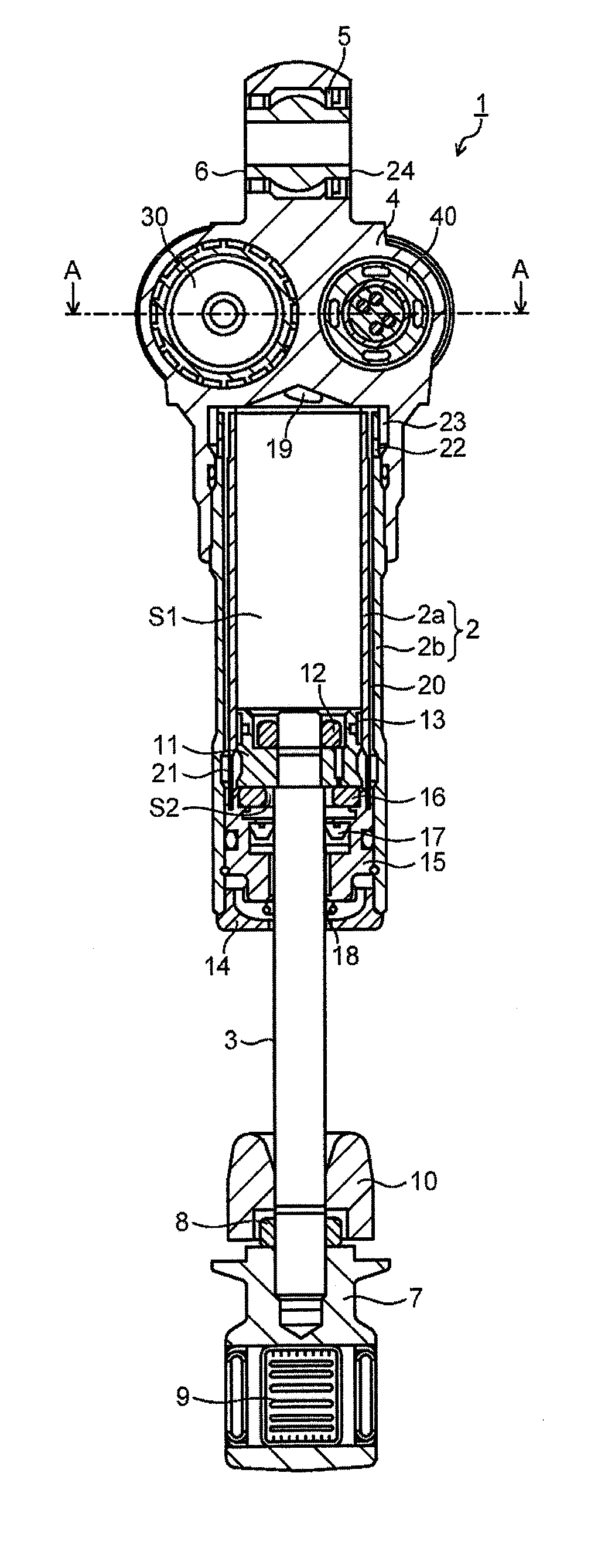
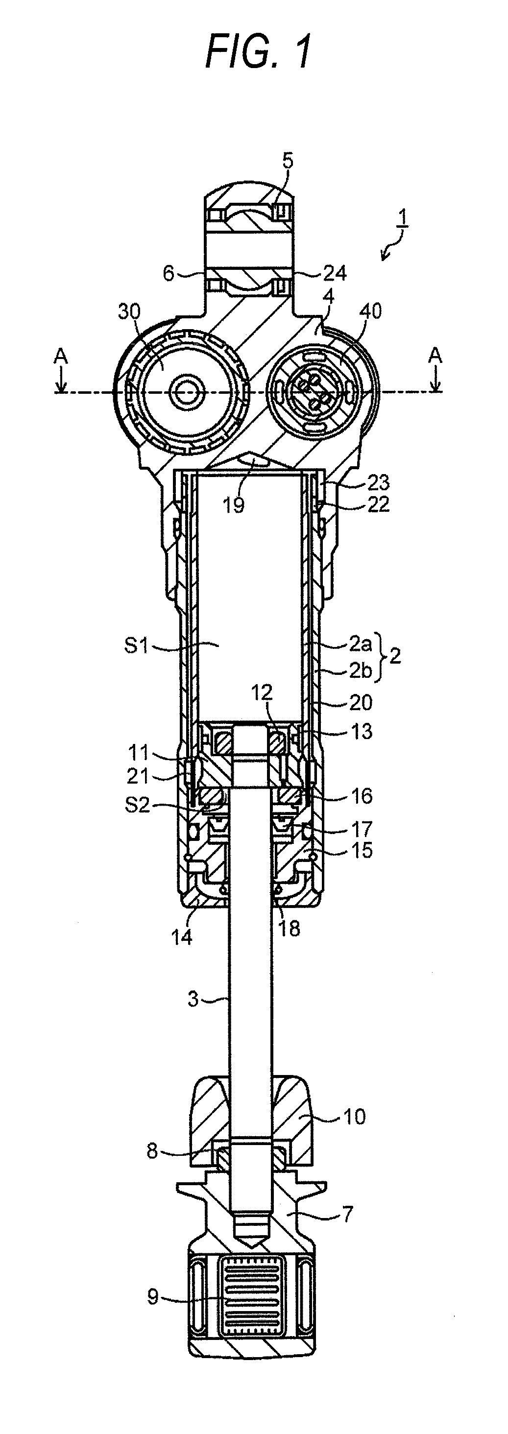
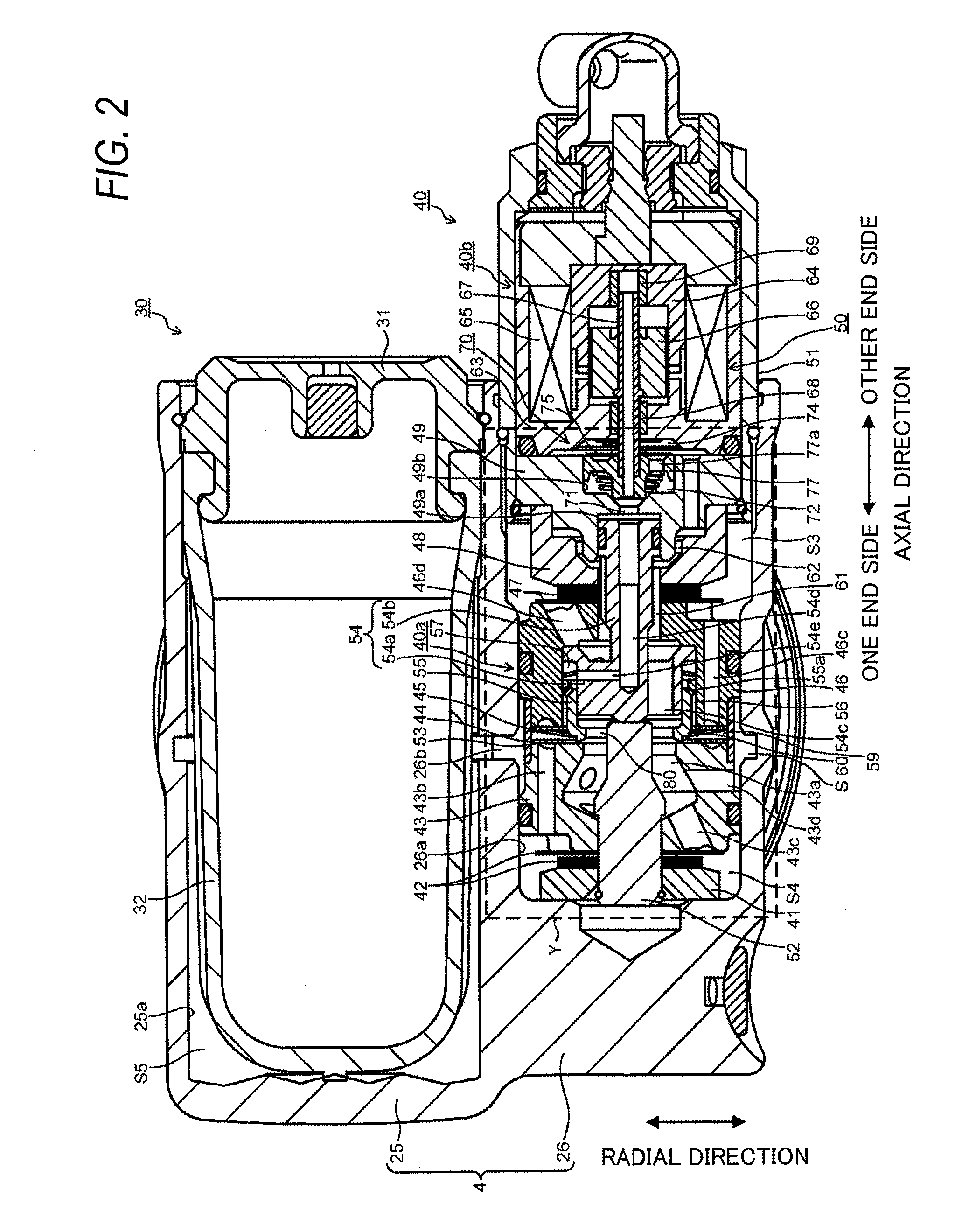
[0030]FIG. 1 is a longitudinal sectional view of a shock absorber 1 in the embodiment. FIG. 2 is an A-A sectional view of FIG. 1. FIG. 3 is an enlarged detailed view of Part Y in FIG. 2.

[0031]The shock absorber 1 in the embodiment is an inverted rear cushion that suspends a rear wheel of a motorcycle on a vehicle body. In the shock absorber 1, as shown in FIG. 1, a part of a piston rod 3 attached to an axle side is inserted from below into an inside of a cylinder 2 attached to a vehicle body side. A not-shown suspension spring is interposed between the cylinder 2 and the piston rod 3.

[0032]The cylinder 2 is configured by an inner cylinder 2a and an outer cylinder 2b that form a concentric double tube. A damper case section 4 is attached to an upper end portion of the cylinder 2. A reservoir 30 and a damping-force generating device 40 explained below are p...


PUM


Abstract

A damping-force generating device included in a shock absorber includes: a main valve that opens and closes for controlling a flow of oil (working fluid) caused by sliding of a piston in a cylinder and thereby generates a damping force; a first pressure chamber and a second pressure chamber separated by the main valve; a compression-side inlet check valve and an extension-side inlet check valve that allow only inflow of the oil into the first pressure chamber; and a compression-side outlet check valve and an extension-side outlet check valve that allow only outflow of the oil from the second pressure chamber. The first pressure chamber and the second pressure chamber are formed in a substantially double-ring structure.

Description

CROSS-REFERENCE TO RELATED APPLICATIONS[0001]This application is based on and claims priority under 35 USC 119 from Japanese Patent Application No. 2014-199703 filed on Sep. 30, 2014, the entire content of which is incorporated herein by reference.BACKGROUND[0002]1. Technical Field[0003]The present invention relates to a shock absorber including a damping-force generating device that controls a flow of working fluid caused by sliding of a piston in a cylinder and thereby generates a damping force.[0004]2. Related Art[0005]As a shock absorber used as a rear cushion that suspends a rear wheel of a motorcycle on a vehicle body, for example, there is a hydraulic shock absorber including a damping-force generating device that controls a flow of oil caused by sliding of a piston in a cylinder and thereby generates a damping force. Various techniques have been proposed concerning such a hydraulic shock absorber.[0006]FIG. 11 is a longitudinal sectional view of a main part of a related-art ...

Claims


Application Information

Patent Timeline
Patent Type & Authority Applications(United States)
IPC IPC(8): F16F9/34F16F9/18
CPCF16F9/18F16F9/34F16F9/465F16F9/469
Inventor MURAKAMI, YOSUKEMIWA, KAZUHIRO
Owner HITACHI ASTEMO LTD
Why Eureka
Try Eureka