Heat pipe

a heat pipe and heat exchanger technology, applied in indirect heat exchangers, heat exchange apparatus, lighting and heating apparatus, etc., can solve the problems of difficult to ensure a space serving as the vapor passage, difficult to improve the flow performance of working fluid, and the evaporating section would be dried out, so as to reduce the heat resistance in the evaporating section, the working fluid can be efficiently evaporated, and the inner section can be enhanced. the effect of capillary pumping

Inactive Publication Date: 2016-03-31
THE FUJIKURA CABLE WORKS LTD
View PDF10 Cites 16 Cited by
  • Summary
  • Abstract
  • Description
  • Claims
  • Application Information

AI Technical Summary

Benefits of technology

[0012]The present invention has been conceived nothing the foregoing technical problems, and it is therefore an object of the present invention is to provide a heat pipe having enhanced evaporation performance and heat transport performance.
[0022]As described, according to the present invention, the groove wick is not filled completely with the metal powder layer so that the working fluid can be returned effectively by the capillary pumping performed by the groove wick. In addition, since the metal powder layer is formed on the inner wall of the groove in the evaporating section, the working fluid in the liquid phase returned thereto can be spread entirely within the evaporating section. Consequently the evaporation area can be enlarged so that the working fluid can be evaporated efficiently. In addition, the working fluid flowing through the groove wick can be returned to the evaporating section efficiently by an enhanced capillary pumping of the inner section of the metal powder layer. Further, since the thickness of the metal powder layer is thus restricted within the above-mentioned range, the heat resistance in the evaporating section can be reduced and heat transport capacity of the heat pipe can be enhanced. Furthermore, the space serving as the vapor passage can be ensured sufficiently so that the working fluid in the vapor phase is allowed to flow through the vapor passage smoothly.

Problems solved by technology

However, since a thickness of the container is reduced, an inner volume of the flat container is rather small and hence it is difficult to improve a flow performance of the working fluid.
If a large wick structure is arranged inside of the flat container to return the working fluid to the evaporating section efficiently, the wick structure shares the most space in the container and hence it is difficult to ensure a space serving as the vapor passage.
If the working fluid cannot be returned to the evaporating section smoothly, the evaporating section would be dried out.
In addition, while the working fluid can be evaporated through a thin portion of the perforated layer, the working fluid may not be evaporated sufficiently through a thick portion of the perforated layer.

Method used


Image

  • Heat pipe
  • Heat pipe
  • Heat pipe

Examples


Embodiment Construction

)

[0033]Hereinafter, a preferred example of the heat pipe according to the present invention will be explained in more detail with reference to the accompanying drawings.

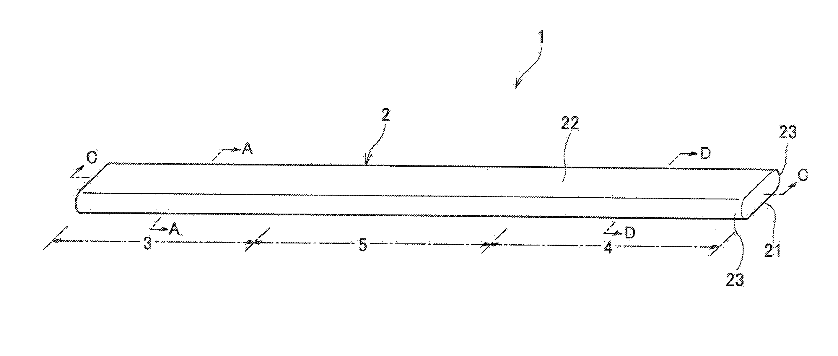
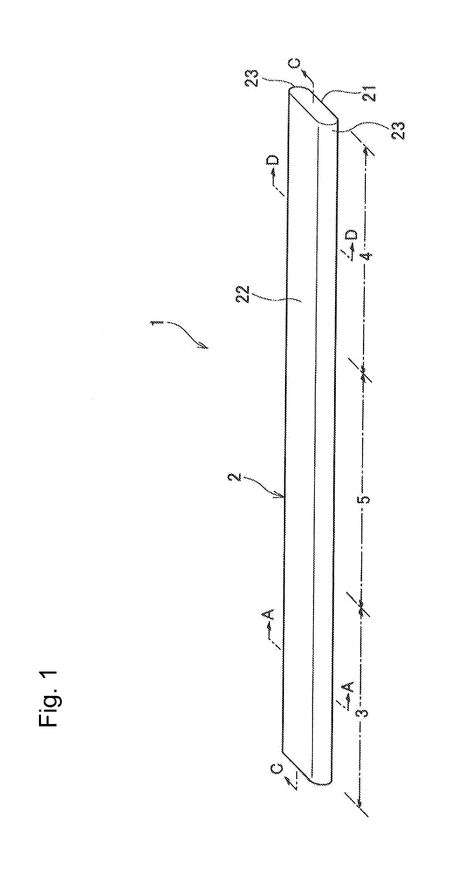
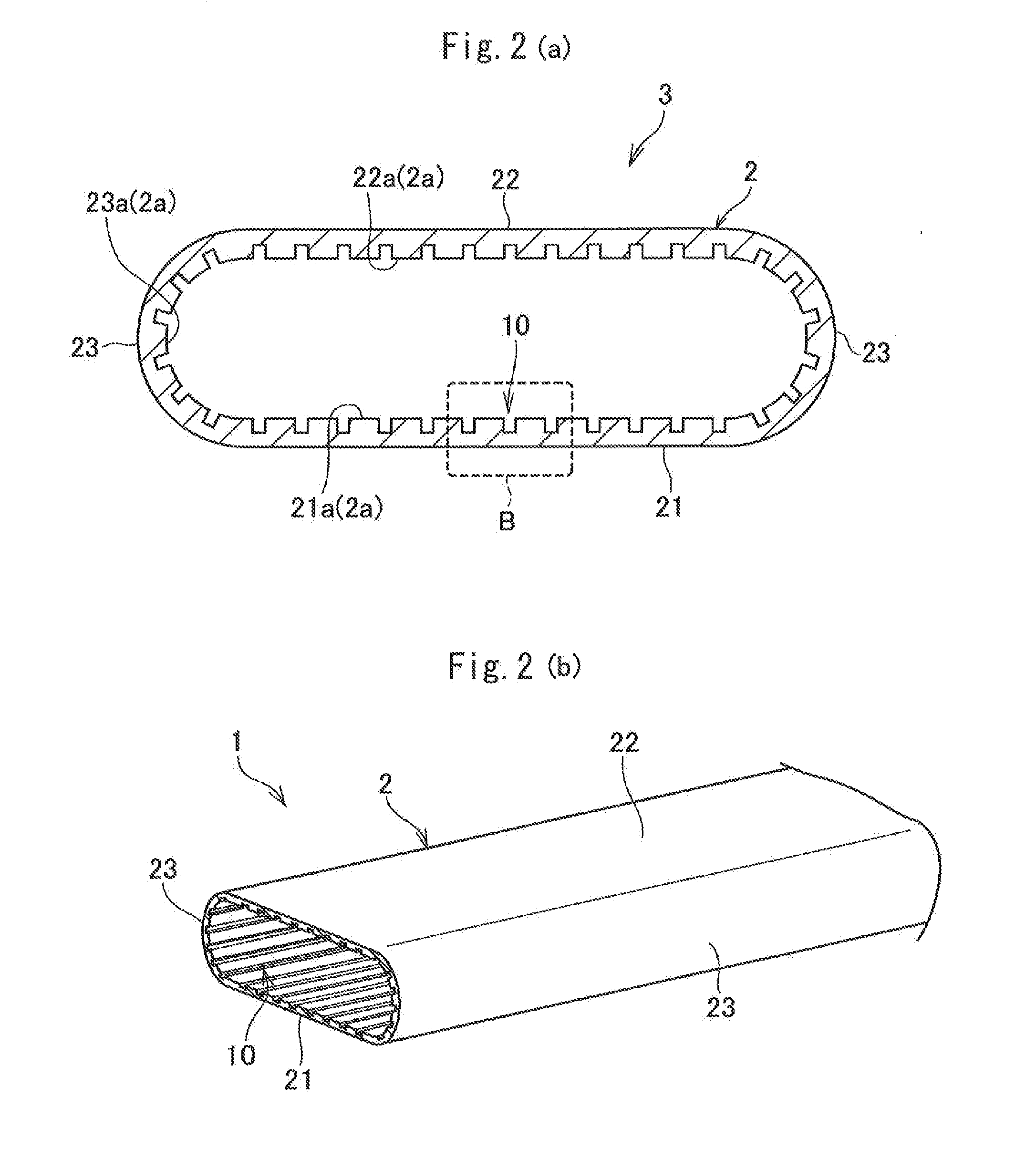
[0034]Referring now to FIG. 1, there is shown a structure of a heat pipe 1 according to the preferred example. The heat pipe 1 is a heat transfer device utilizing a latent heat of phase changeable working fluid encapsulated in a sealed container 2 as a straight rectangular tube.

[0035]The container 2 is a hollow flattened rectangular tube having a thickness narrower than a width, and both longitudinal ends thereof are sealed. In an inner space of the container 2, a width dimension is accordingly larger than a thickness dimension. The container 2 is made of metal material having excellent heat conductivity such as copper, steel and aluminum.

[0036]For example, the container 2 is formed by pressing a metal tubular material into a flat shape. Specifically, the container 2 thus formed is comprised of a first flat wall 21 a...


PUM


Abstract

A heat pipe for improving heat transport performance by reducing heat resistance in an evaporating section is provided. The heat pipe comprises a groove wick extending in the longitudinal direction from the evaporating section to the condensing section through the insulated section in the container. A metal powder layer formed of metal powder adhering to the inner wall of the groove wick is arranged in the evaporating section. The metal powder layer is formed into the groove wick having a predetermined thickness.

Description

[0001]The present invention claims the benefit of Japanese Patent Application No. 2014-200493 filed on Sep. 30, 2014 with the Japanese Patent Office, the disclosure of which is incorporated herein by reference in its entirety.BACKGROUND[0002]1. Field of the Invention[0003]The present invention relates to an art of a heat pipe having a wick structure.[0004]2. Discussion of the Related Art[0005]Heat pipes have been widely used to transport heat in the form of latent heat of working fluid. The conventional heat pipe is comprised of a tubular container sealed at both ends, and phase changeable working fluid encapsulated in the container. The working fluid is evaporated by a heat of a heat generating element and flows toward a low temperature site.[0006]In general, one end of the heat pipe is brought into contact to a heat generating element, and other end of the heat pipe is connected to a radiation member. The end portion of the heat pipe brought into contact to the heat generating ele...

Claims


Application Information

Patent Timeline
Patent Type & Authority Applications(United States)
IPC IPC(8): F28D15/04
CPCF28D15/04F28D15/0233F28D15/046F28F2255/18
Inventor AHAMED, MOHAMMAD, SHAHEDSAITO, YUJI
Owner THE FUJIKURA CABLE WORKS LTD
Why Eureka
Try Eureka