Flow test machine and an associated measurement method, as well as an associated cleaning process

a flow test machine and measurement method technology, applied in the direction of cleaning process, direct flow property measurement, instruments, etc., can solve the problem of not being able to apply a weight force with an additional force, and achieve the effect of low amount, fast filling and particularly dimensional stability

Active Publication Date: 2016-03-31
ZWICKROELL GMBH & CO KG
View PDF2 Cites 10 Cited by
  • Summary
  • Abstract
  • Description
  • Claims
  • Application Information

AI Technical Summary

Benefits of technology

[0072]During the implementation of a cleaning step which is connected to the measurement method, it is advantageous if the temperature is maintained at a predetermined temperature value. A temperature control on the flow test machine ensures that a flow temperature of the test material is present. The temperature control is, for example, able to be executed by at least one temperature sensor, in particular at the test channel. The heat capacity of the flow test machine, in particular a test channel cylinder, is preferably sufficient such that the test mass remains fluid during a test time.
[0073]It is favorable for an at least partially automatic operation of a flow test machine if a control unit is provided. The control unit can, for example, control a test cylinder or also an actuator of a bracket. The control unit can also lead an arm to a test weight magazine or to a piston magazine. It is particularly advantageous if the control unit meters the actuating additional force. An actuating additional force, a cleaning force, is applied to the cleaning piston by the control unit. It is, for example, possible, to increase the actuating additional force exerted on the cleaning piston using the control unit at a movement obstacle present due to an impurity in the test channel, in particular in the case of a recognized movement obstacle, until the movement obstacle is eliminated. According to another aspect of the control unit, the cleaning piston which is subject to, for example, a force of a test weight or of a cleaning weight, so a cleaning weight force, can be decelerated in particular before reaching a nozzle. A control of the actuating additional force by the control unit for application on the test piston or the compression piston is also particularly advantageous. A control of the actuating additional force occurs sequentially according to requirement. Within the individual steps of the cleaning method, in other words for the execution of a cleaning step or of a partial step, the actuating additional force is able to be controlled and is in particular able to be varied. For example, an additional force which is lower in amount can be applied to the cleaning piston during retraction into the test channel than during extraction from the test channel.
[0074]The test channel is particularly dimensionally stable if it is arranged in a cylindrical body. Pressure forces in the test cylinder can therefore only cause a radially symmetrical deformation which is low even in the case of a low mass of the body such that test results remain unimpaired. The test channel is preferably arranged to be unrelenting with regard to a drive unit. The filling opening can have a conical channel, with which a quick filling of the test channel is favored and in particular the insertion of a piston is facilitated. Preferably a switchable directional channel is provided between the nozzle and the weighing device which has a preferably lotus-like, repellant surface quality. In a switch position of the directional channel, sections of the test material which resulted due to the press-out step are supplied to a collecting tank. In a second switch position, at least one section of the test mass is supplied to the weighing device. Therefore, particularly accurate weighing of the test mass can be implemented without loss of time.
[0075]A flow test machine according to the invention is also able to be used for tests for material testing which represents a further development, in particular based on existing standards. Due to the numerous variants and combination possibilities, advantageous embodiments of the described flow test machine as well as test variants result, in particular due to their control, which are considered below or as a further development of the standards. For example, test masses can be pressed out by exchangeable nozzles with variable force profiles. From (individual) test to (individual) test, the material properties can be determined little by little more precisely. Error influences are, in particular with the aid of the control unit, able to be removed and eliminated.

Problems solved by technology

A lift device is provided which should, however, work with chains and therefore is probably not able to be used for applying a weight force with an additional force.

Method used


Image

  • Flow test machine and an associated measurement method, as well as an associated cleaning process
  • Flow test machine and an associated measurement method, as well as an associated cleaning process
  • Flow test machine and an associated measurement method, as well as an associated cleaning process

Examples


Embodiment Construction

[0011]The object of the invention is solved by a flow test machine according to claim 1. An appropriate procedure for conducting a melt viscosity test can be found in claim 14. To achieve comparable measurement results that are as good as possible with a flow test machine, claim 19 offers an inventive method for cleaning a flow test machine. Advantageous developments can be taken from the dependent claims.

[0012]The melt mass flow rate and the melt volume flow rate are material properties, which among other things depend on the chemical composition of the examined plastic or the quality of the used plastic. Plastics are often present as polymers, whose fluidity can be slowed by chain lengths or even by a number of bridging bonds between polymer chains. For many types of plastics, values of flow rates that suggest an acceptable quality level of the plastic, are stored in tabular form, for example in relevant manuals or manufacturer databases. Deviations from tabulated stored values ma...


PUM

PropertyMeasurementUnit
temperaturesaaaaaaaaaa
massaaaaaaaaaa
weightaaaaaaaaaa

Abstract

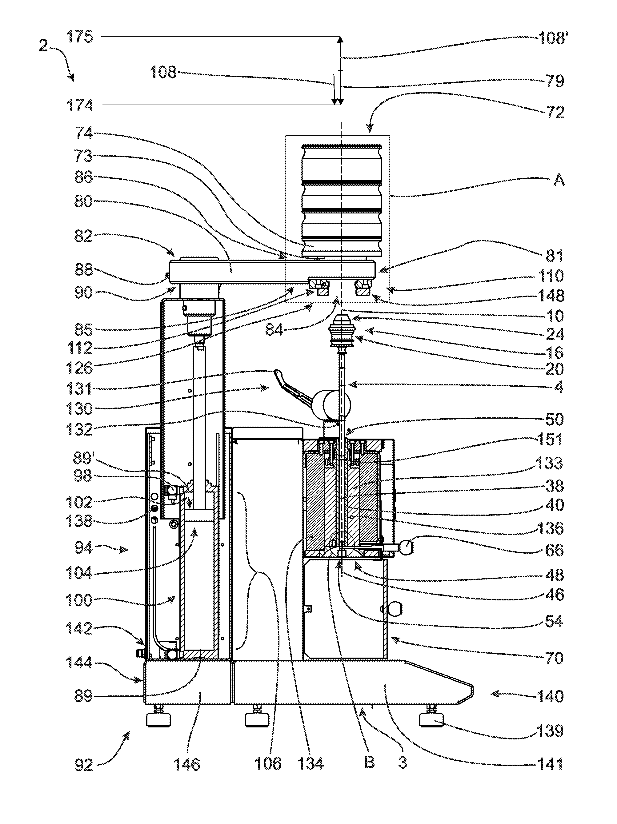
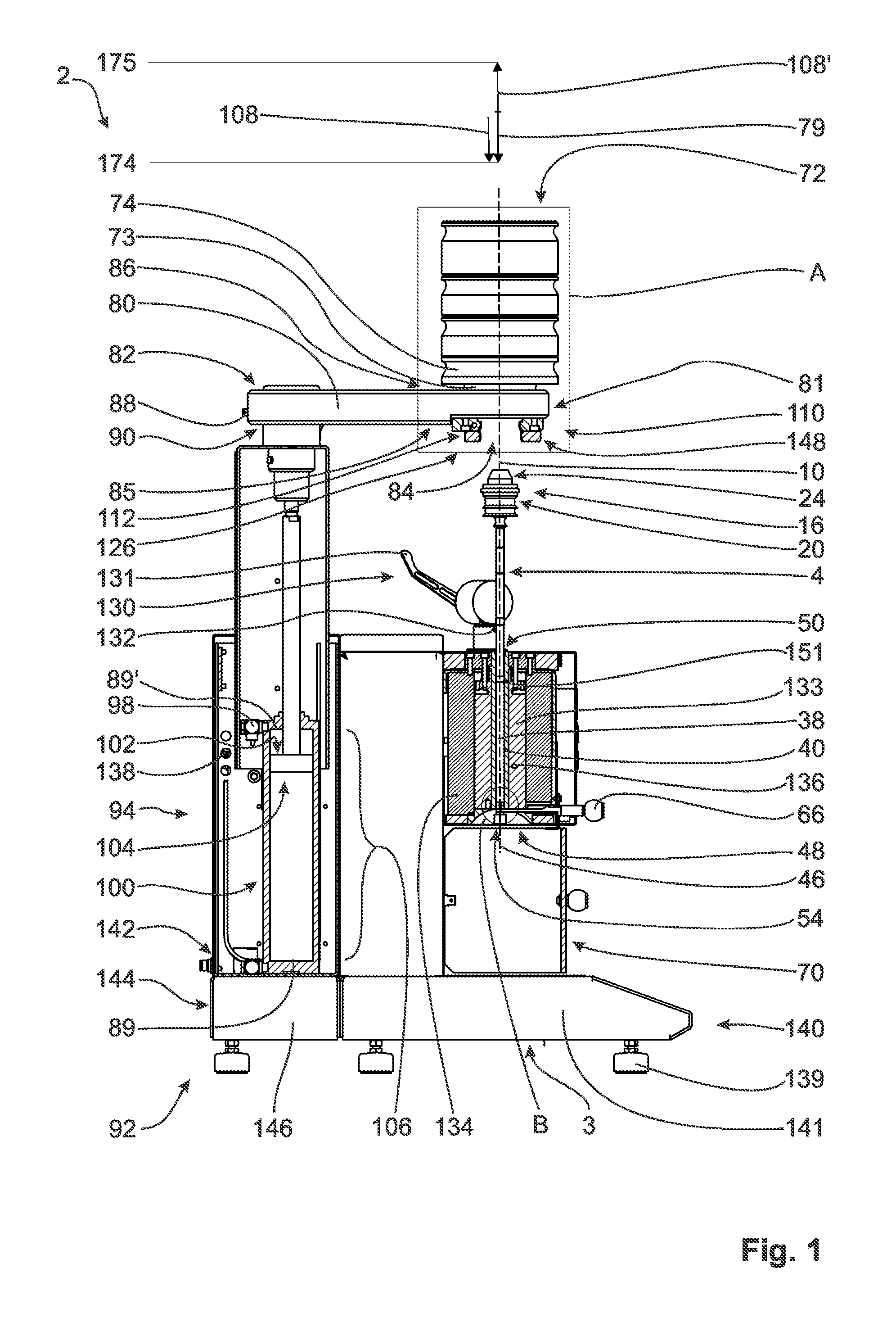
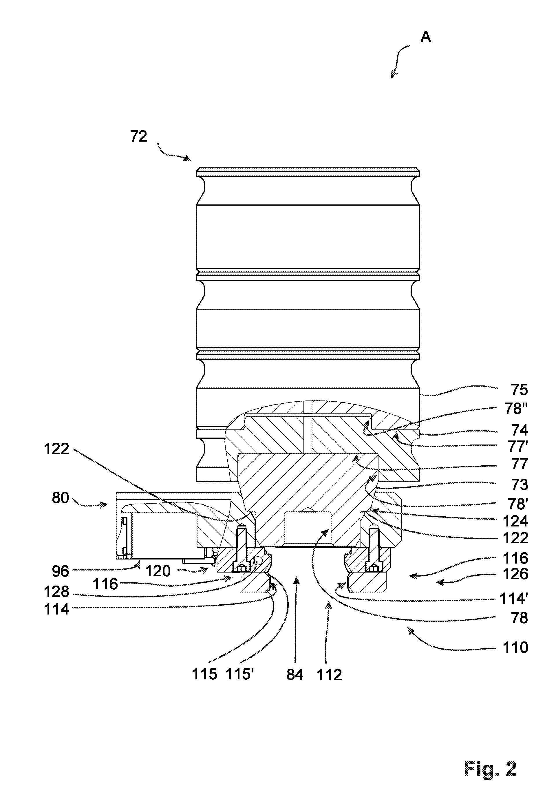
A flow test machine 2 which, for example, is able to be used for viscosity tests on plastics, comprises a test piston 4, a test channel 38, at least one test weight 72 and a drive unit 92. The test piston 4 is able to move through the test channel 38 by means of a weight force 79 of the test weight 72. The test weight 72 is able to be loaded by an actuating additional force 108, 108′ by means of the drive unit 92 between a starting position 151 and an end position. The actuating additional force 108 enables a movement of the test piston 4 in the direction of the weight force 79, said movement being accelerated in comparison with an effect of the weight force 79. In a melt viscosity test, after a heating step, a thermoplastic plastic is pressed through a test channel 38 by a test piston 4. In a measurement preparation step and/or a cleaning step, the test mass is lowered along a weight force direction 79 under the influence of an actuating additional force 108, 108′. In a method for cleaning, a cleaning step is undertaken by means of an actuating additional force 108, 108′ from the drive unit 92, said drive unit 92 serving to drive a test piston movement during a melt viscosity test.

Description

PRIORITY[0001]The present application claims the benefit of DE 10 2014 114 117.2, filed Sep. 29, 2014, which is herein incorporated by reference in its entirety.[0002]In the testing of thermoplastics, flow test machines, also referred to as a capillary viscometers by some manufacturers, are used, with which fusible or sliding plastics in particular are tested on their flow behavior during pressing. Some of the testing machines work with the acquisition of melt mass flow rates; others work with melt volume flow rates. Melt mass flow rates and melt volume flow rates can be converted into each other taking into account different test conditions for a known density of the melt. In both flow rate measurements, time is always a measureable entity. The present invention therefore relates to a flow test machine, in particular for viscosity tests, for example of plastics, according to the preamble of claim 1, a method for testing of viscosities according to the preamble of claim 14, as well ...

Claims


Application Information

Patent Timeline
Patent Type & Authority Applications(United States)
IPC IPC(8): G01N11/02B08B9/04
CPCB08B9/04G01N11/02G01N11/04G01N3/10G01N33/442
Inventor FLOCK, MARCUSGANSER, FRANZKINDERMANN, ULRICHVOLZKE, DAVID
Owner ZWICKROELL GMBH & CO KG
Why Eureka
Try Eureka