
Optical unit, optical apparatus using the same, light source apparatus, and projection display apparatus

a technology of optical equipment and light source equipment, applied in the direction of instruments, lighting and heating equipment, optical elements, etc., can solve the problems of deteriorating the brightness of the projected image, reducing the light output of the lds, so as to reduce the light utilization efficiency

Active Publication Date: 2016-03-31
CANON KK
View PDF2 Cites 13 Cited by
  • Summary
  • Abstract
  • Description
  • Claims
  • Application Information

AI Technical Summary

Benefits of technology

This patent is about an optical device that improves the efficiency with which light is used and makes the light source smaller. It achieves this by using reflective surfaces that guide light from multiple sources to a lens. The shapes of the reflective surfaces cause the light to converge and become more efficient as it travels through the device. This results in a smaller light source and improved optical performance.

Problems solved by technology

However, light output of the LDs is reduced at a higher temperature, and thus when the LDs are densely arranged giving a priority to downsizing of the projector, the LDs give heat to each other and the light output of the LDs is reduced, which deteriorates brightness of a projected image.
However, when the arrangement intervals become wider, light fluxes exiting the group of LDs become thicker and a size of a subsequent optical element is also increased, which is not desirable in terms of cost and weight.
However, in the structure described in Japanese Patent Application Laid-Open No. 2011-65770, the reflective surfaces of the mirrors are planar and thus it is difficult to condense parallel light fluxes reflected on the mirrors to a small area on the fluorescent body.
If a condensing spot on the fluorescent body is large, parallelism of light lowers when the light is incident on the subsequent optical system, and light utilization efficiency can be deteriorated.
However, with the structure described in United States Patent Publication Application No. 2014 / 0111775, when the number of LDs increases to obtain higher luminance, the paraboloid mirror becomes wider in area and deeper, which may increase the size of the light source apparatus.

Method used


Image

  • Optical unit, optical apparatus using the same, light source apparatus, and projection display apparatus
  • Optical unit, optical apparatus using the same, light source apparatus, and projection display apparatus
  • Optical unit, optical apparatus using the same, light source apparatus, and projection display apparatus

Examples


Embodiment Construction

[0023]An exemplary embodiment according to the present invention will be described below with reference to the drawings. The shapes or relative arrangements of the components described in the exemplary embodiment should be changed as needed based on a structure of an apparatus to which the present invention is applied, or various conditions. That is, the shapes or relative arrangements of the components are not defined to limit the scope of the present invention within the following exemplary embodiment.

[Structure of Projection Display Apparatus]

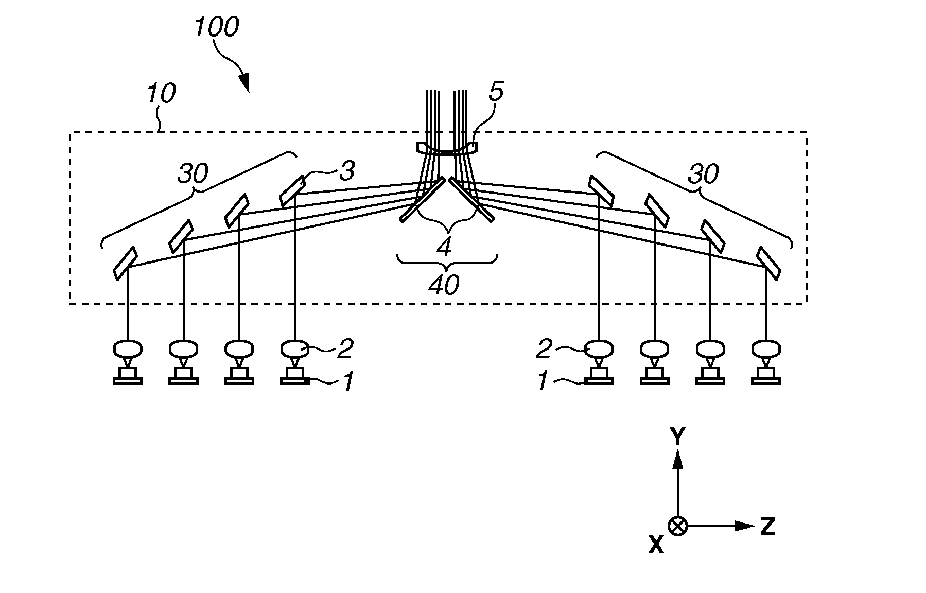
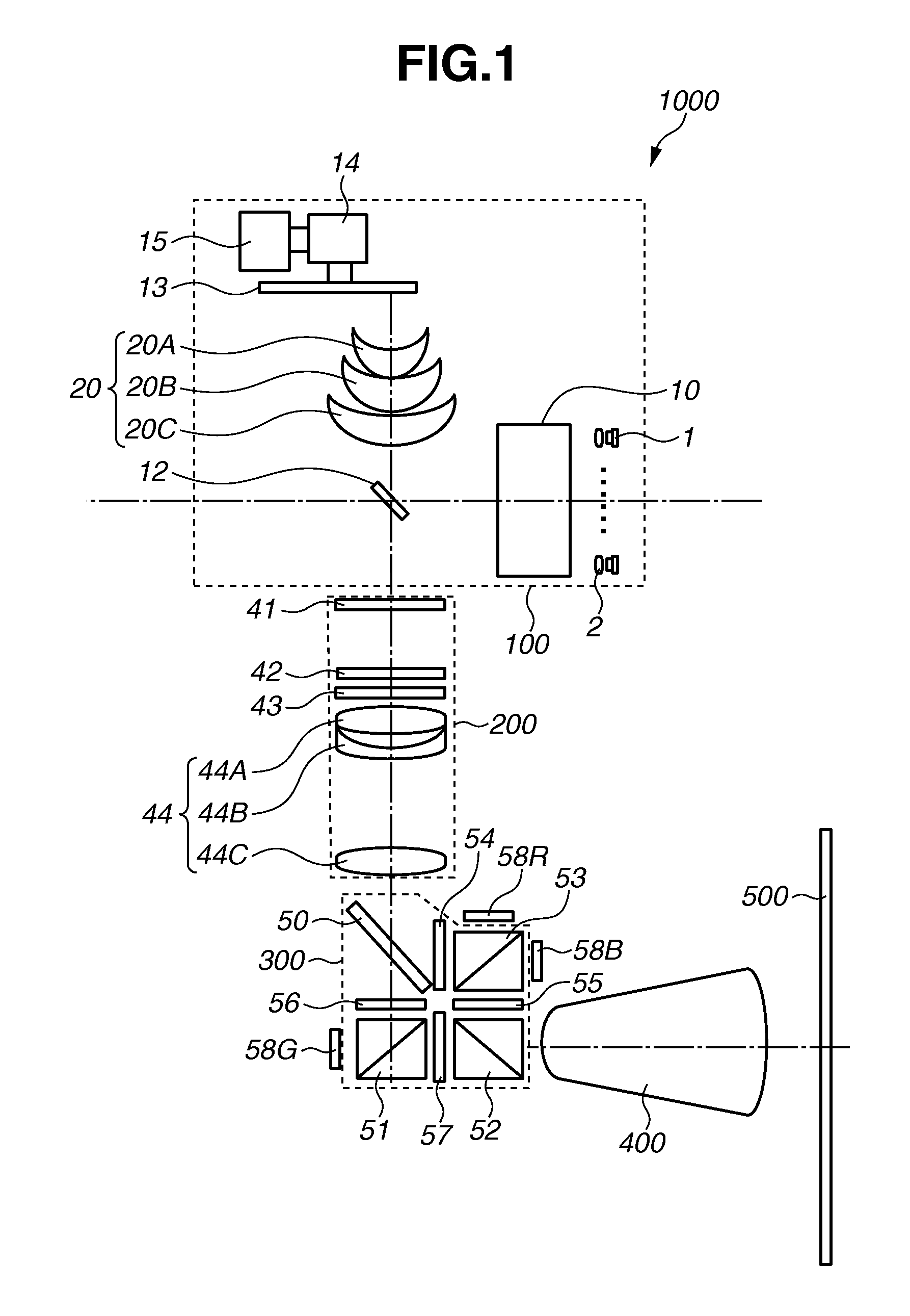
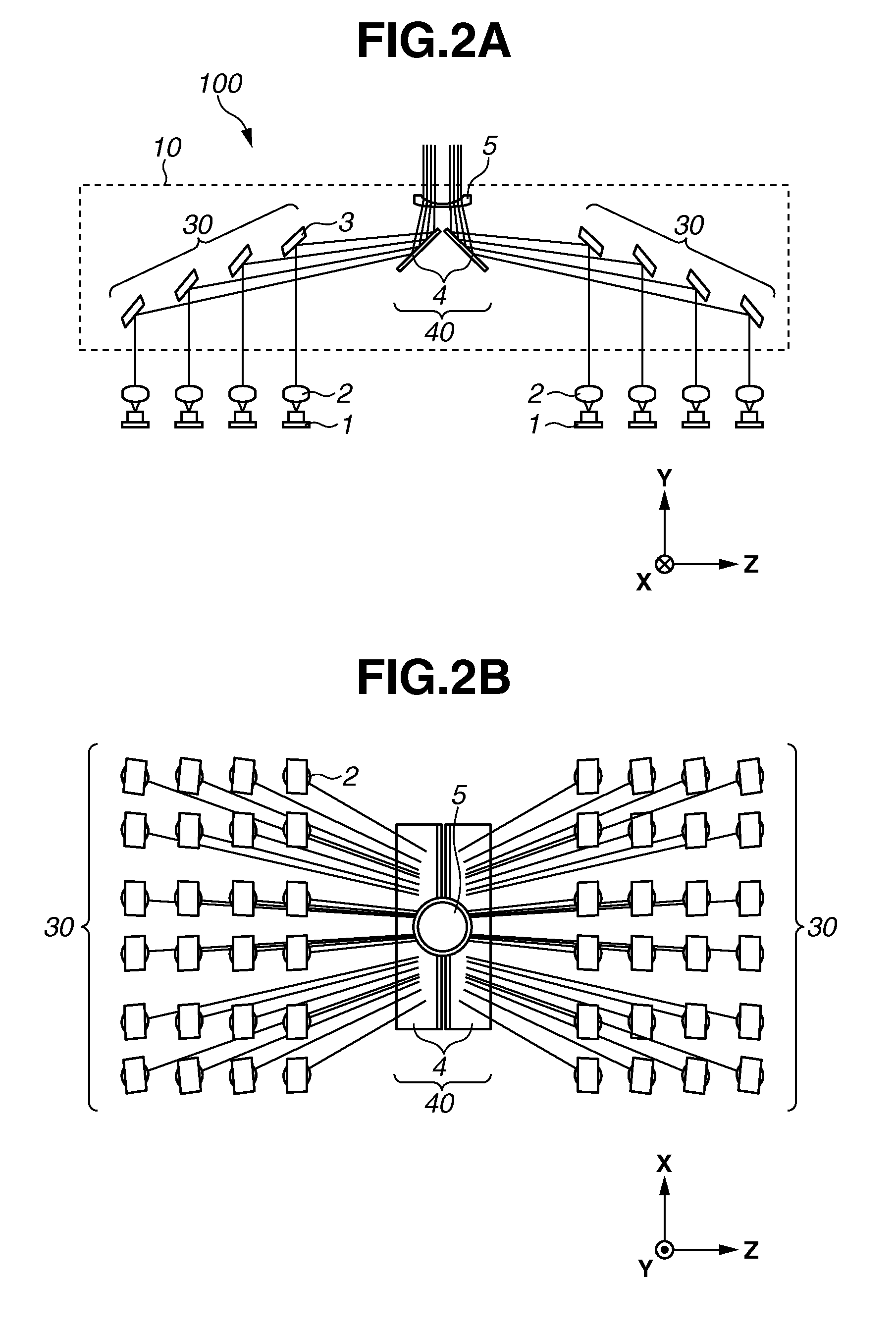
[0024]The structure of a projector 1000 mounted with an optical apparatus according to the exemplary embodiment of the present invention will be first described with reference to FIG. 1.

[0025]The projector (projection display apparatus) 1000 includes a light source apparatus 100, an illumination optical system 200, a color separation-combination system 300, and a projection lens 400. With this structure, the projector 1000 can project an ima...


PUM


Abstract

An optical unit includes a plurality of paraboloid mirrors configured to reflect light fluxes from a plurality of LDs and to guide them to a concave lens. The light fluxes from the paraboloid mirrors are a plurality of convergent light fluxes, and the paraboloid mirrors reflect the light fluxes from the LDs such that as the convergent light fluxes travel farther away from the paraboloid mirrors, distances therebetween become shorter.

Description

BACKGROUND OF THE INVENTION[0001]1. Field of the Invention[0002]The present invention relates to an optical unit, an optical apparatus using the same, a light source apparatus, and a projection display apparatus. The present invention particularly relates to a light source apparatus using a solid light source such as a semiconductor laser as a light source.[0003]2. Description of the Related Art[0004]In recent years, there has been developed a projector which irradiates a fluorescent body with light fluxes emitted from high-output laser diodes (LD) as excitation light and uses wavelength-converted fluorescent light.[0005]It is presumed that many LDs are arranged and used to realize high luminescence with in a projector. However, light output of the LDs is reduced at a higher temperature, and thus when the LDs are densely arranged giving a priority to downsizing of the projector, the LDs give heat to each other and the light output of the LDs is reduced, which deteriorates brightness...

Claims


Application Information

Patent Timeline
IPC IPC(8): G03B21/20G02B5/10G02B27/10G02B27/14
CPCG03B21/2066G03B21/204G02B27/106G02B27/141G02B5/10G03B21/208G03B21/2013G03B21/2033
Inventor INOKO, KAZUHIROSUDO, TAKASHI
Owner CANON KK
Learn More