
Wireless charging equipment, terminal, wireless charging system comprising the same, control method thereof and non-transitory computer readable storage medium having computer program recorded thereon

a wireless charging and wireless charging technology, applied in the direction of data switching current supply, data switching details, subscription services, etc., can solve the problems of charging signal not provided and inefficient aspects, and achieve the effect of improving the system efficiency of the entire wireless charging system, improving convenience of use, and enlarging the application range of the wireless charging system

Active Publication Date: 2016-03-31
SK PLANET CO LTD
View PDF8 Cites 11 Cited by
  • Summary
  • Abstract
  • Description
  • Claims
  • Application Information

AI Technical Summary

Benefits of technology

This patent describes a way to authenticate a device and determine if it is pre-registered with a wireless charging system, without needing an extra component. This improves efficiency and determines if the device is a terminal or an affiliated company. It also tracks if the device is being charged and if the user is pre-registered, which can improve system efficacy and provide additional services to the device based on charging start time and access time information.

Problems solved by technology

The wireless charging equipment communicates with a terminal adjacent to the corresponding wireless charging equipment, and the corresponding wireless charging equipment transmits a charging signal to the corresponding terminal, the terminal charges a battery provided in the corresponding terminal based on the charging signal, and thus, there is an inefficient aspect in that the charging signal is not provided to a pre-authorized terminal.

Method used


Image

  • Wireless charging equipment, terminal, wireless charging system comprising the same, control method thereof and non-transitory computer readable storage medium having computer program recorded thereon
  • Wireless charging equipment, terminal, wireless charging system comprising the same, control method thereof and non-transitory computer readable storage medium having computer program recorded thereon
  • Wireless charging equipment, terminal, wireless charging system comprising the same, control method thereof and non-transitory computer readable storage medium having computer program recorded thereon

Examples


first embodiment

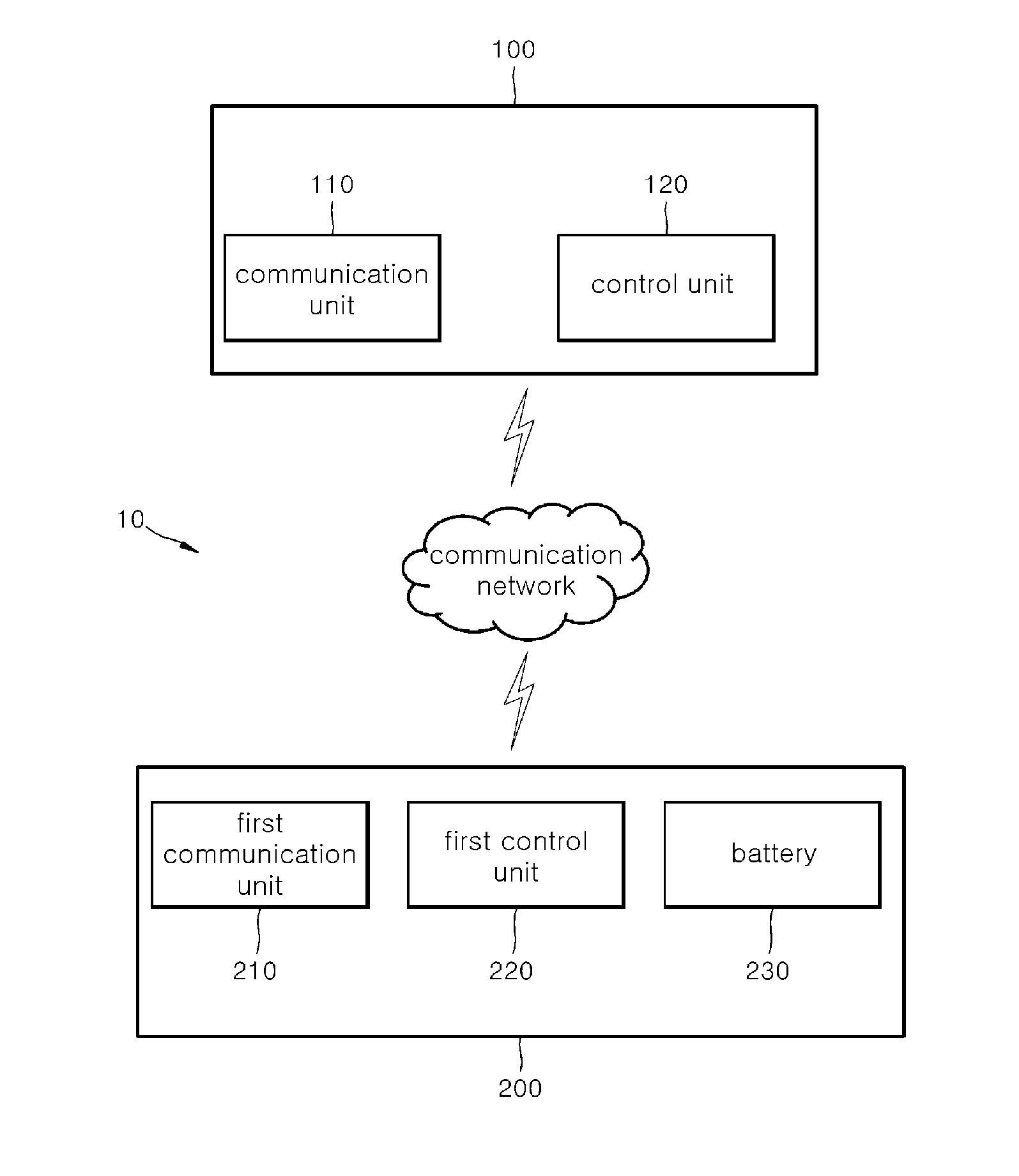
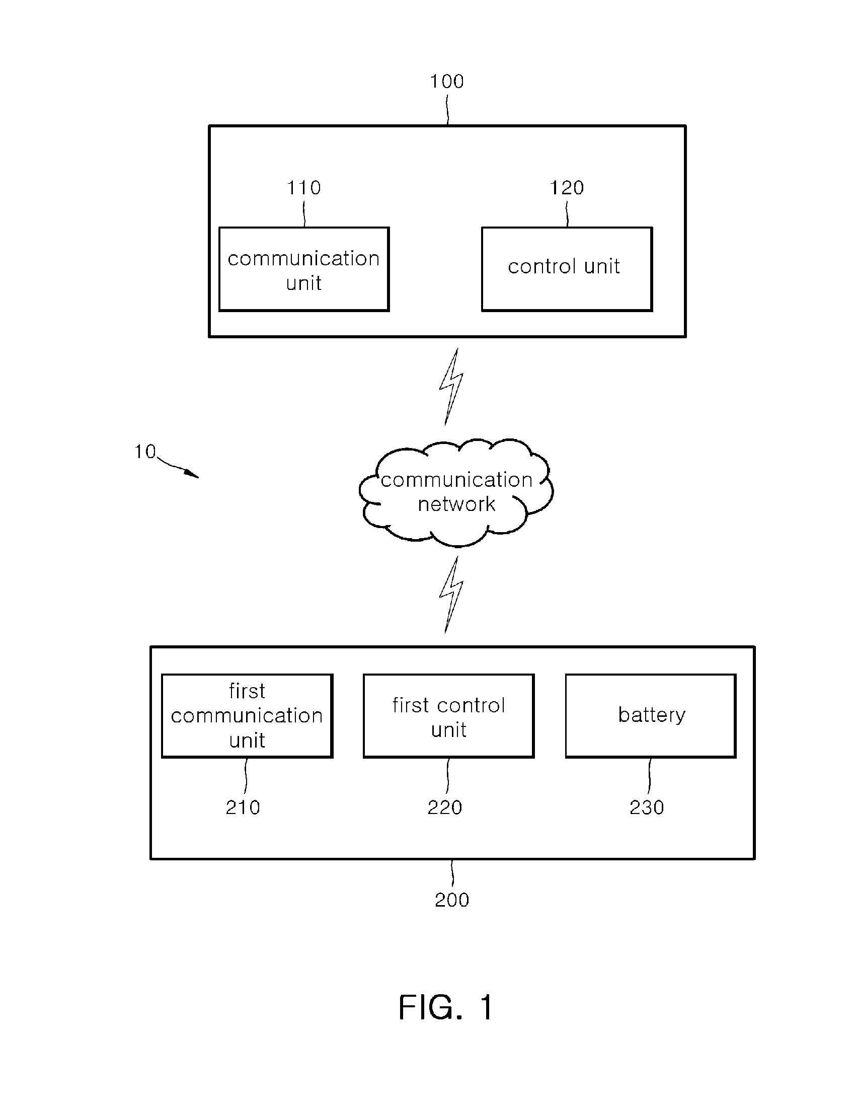
[0187]FIG. 5 is a flowchart illustrating a control method of a wireless charging system according to the present invention.

[0188]First, in A4WP scheme wireless charging, wireless charging equipment 100 (alternatively, a PTU) transmits a power beacon signal at a predetermined time interval.

[0189]As an example, the wireless charging equipment 100 transmits (alternatively, propagates) the power beacon signal to a first terminal and a second terminal which include PRUs adjacent to the corresponding wireless charging equipment 100, respectively (S510).

[0190]Thereafter, the terminal 200 adjacent to the corresponding wireless charging equipment 100 receives the power beacon signal transmitted from the wireless charging equipment 100.

[0191]Further, the terminal 200 generates a PRU advertisement signal in response to the received power beacon signal and transmits the generated PRU advertisement signal to the wireless charging equipment 100.

[0192]As an example, each of the first terminal and ...

second embodiment

[0218]FIG. 6 is a flowchart illustrating a control method of a wireless charging system according to the present invention.

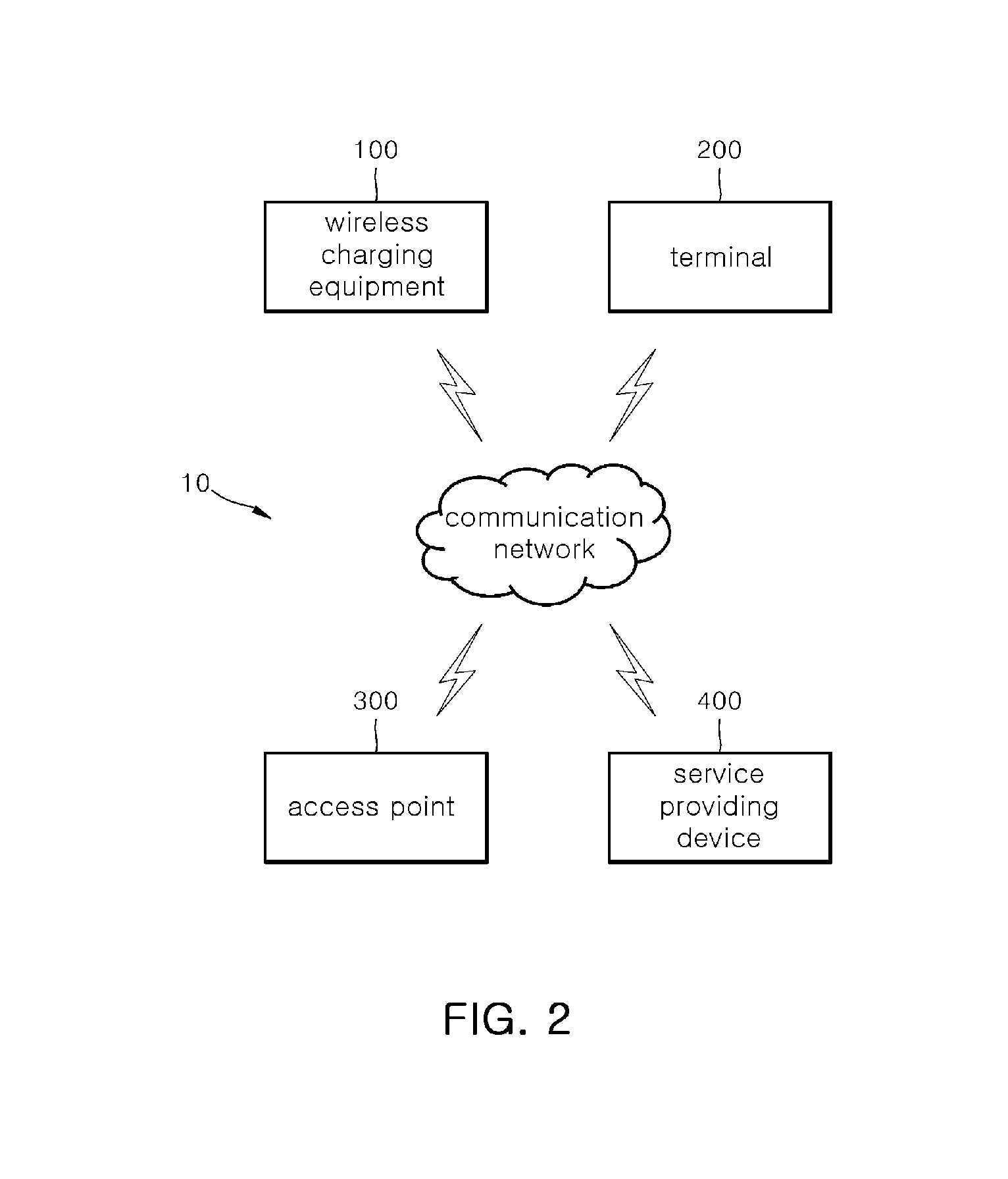
[0219]First, the wireless charging equipment 100 is connected with (alternatively, starts to communicate with) the terminal 200 or transmits the charging signal to the terminal 200 to generate a personal information provision inquiry signal in a state where the battery 230 included in the terminal 200 is charging. Here, the personal information provision inquiry signal may be a signal for inquiring whether to agree to collect (alternatively, acquire) the internet usage information of the corresponding terminal 200 in order to use the internet for free through the access point 300 installed in the store including the wireless charging equipment 100 in the terminal 200 while charging.

[0220]Further, the wireless charging equipment 100 transmits the generated personal information provision inquiry signal to the corresponding terminal 200.

[0221]As an example, when th...

third embodiment

[0243]FIG. 7 is a flowchart illustrating a control method of a wireless charging system according to the present invention.

[0244]First, in A4WP scheme wireless charging, wireless charging equipment 100 (alternatively, a PTU) transmits a power beacon signal at a predetermined time interval. Further, a terminal 200 adjacent to the corresponding wireless charging equipment 100 receives the power beacon signal transmitted from the wireless charging equipment 100.

[0245]Further, the terminal 200 generates a PRU advertisement signal in response to the power beacon signal and transmits the generated PRU advertisement signal to the wireless charging equipment 100. Here, the PRU advertisement signal includes unique information (alternatively, a sharing ID) of a PRU included in the corresponding terminal 200, version information of the corresponding PRU, a manufacturing number of the corresponding PRU, identification information of the corresponding terminal 200, and the like. In this case, th...


PUM


Abstract

Provided are wireless charging equipment, a terminal, a wireless charging system comprising the same, a control method thereof, and a non-transitory computer readable storage medium having computer program recorded thereon. That is, the present invention performs a charging function based on a charging signal in the corresponding terminal by transmitting the charging signal to only the terminal corresponding to a communication provider or an affiliated company pre-registered in the wireless charging equipment to provide a charging function to only the pre-registered terminal with respect to a terminal to use a wireless charging infrastructure, easily and conveniently perform an authentication function for the terminal without a separate additional component, and improve operation efficiency of the entire wireless charging system.

Description

CROSS-REFERENCE TO RELATED APPLICATION[0001]This application claims the benefit of Korean Application Nos. 10-2014-0043452 filed on Apr. 11, 2014, 10-2014-0071232 filed on Jun. 12, 2014 and 10-2014-0076773 filed on Jun. 23, 2014 with the Korean Intellectual Property Office, the disclosure of which is incorporated herein by reference.BACKGROUND OF THE INVENTION[0002]1. Field of the Invention[0003]The present invention relates to wireless charging equipment, a terminal, a wireless charging system comprising the same, a control method thereof, and a non-transitory computer readable storage medium having computer program recorded thereon, and more particularly, to wireless charging equipment, a terminal, a wireless charging system comprising the same, a control method thereof, and a non-transitory computer readable storage medium having computer program recorded thereon capable of performing a charging function based on a charging signal in a corresponding terminal by transmitting the c...

Claims


Application Information

Patent Timeline
Patent Type & Authority Applications(United States)
IPC IPC(8): H02J7/02H02J7/04
CPCH02J7/042H02J7/025H02J50/80H04L12/10H04W4/60H02J7/00034H02J50/12H02J50/20H02J7/00036H02J7/00045
Inventor PARK, YON, WONKIM, HYUN, WOOKIM, JOON, SOKKANG, SEONG, WOOKNA, SEUNG, WONSEO, KYEONG, HOJIN, HYUNG, MIN
Owner SK PLANET CO LTD
Learn More