Wideband rectenna and rectifying apparatus for rectenna

Active Publication Date: 2016-03-31
AGENCY FOR DEFENSE DEV
View PDF1 Cites 191 Cited by
  • Summary
  • Abstract
  • Description
  • Claims
  • Application Information

AI Technical Summary

Benefits of technology

[0009]Therefore, to obviate the aforementioned drawbacks, an aspect of the detailed description is to provide a wideband r

Problems solved by technology

The constraints on the design of MPT systems are the choice of an operating frequency and a system configuration of a transmitter and a receiver.
However

Method used


Image

  • Wideband rectenna and rectifying apparatus for rectenna
  • Wideband rectenna and rectifying apparatus for rectenna
  • Wideband rectenna and rectifying apparatus for rectenna

Examples


Example

[0058]The present invention may be varied by various ways and have various embodiments, and specific embodiments will be illustrated in the accompanying drawings and described in detail.

[0059]However, this is not to limit the present invention to the specific embodiments, and it should be understood that the present invention includes all the variations, equivalents and replacements belonging to the scope and technical range of the present invention.

[0060]The terms including an ordinal number such as first, second, etc. can be used to describe various elements, but the elements should not be limited by those terms. The terms are used merely for the purpose to distinguish an element from the other element. For example, a first element may be named to a second element, and similarly, a second element may be named to a first element without departing from the scope of right of the invention. The term “and / or” includes any and all combinations of one or more of the associated listed ite...


PUM


Abstract

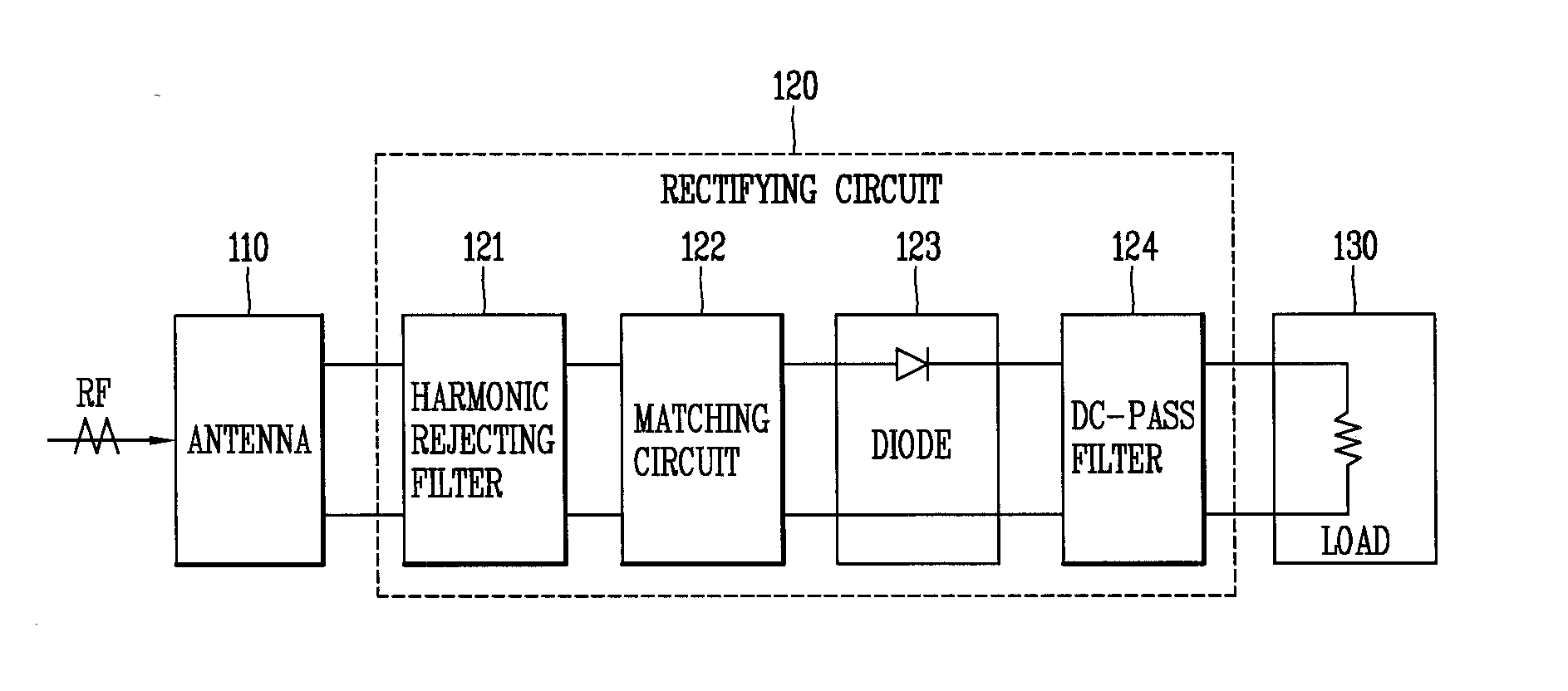
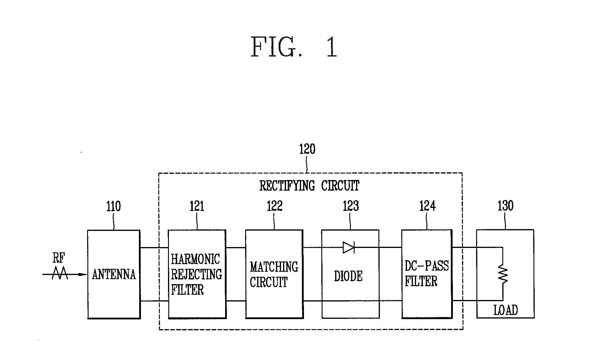
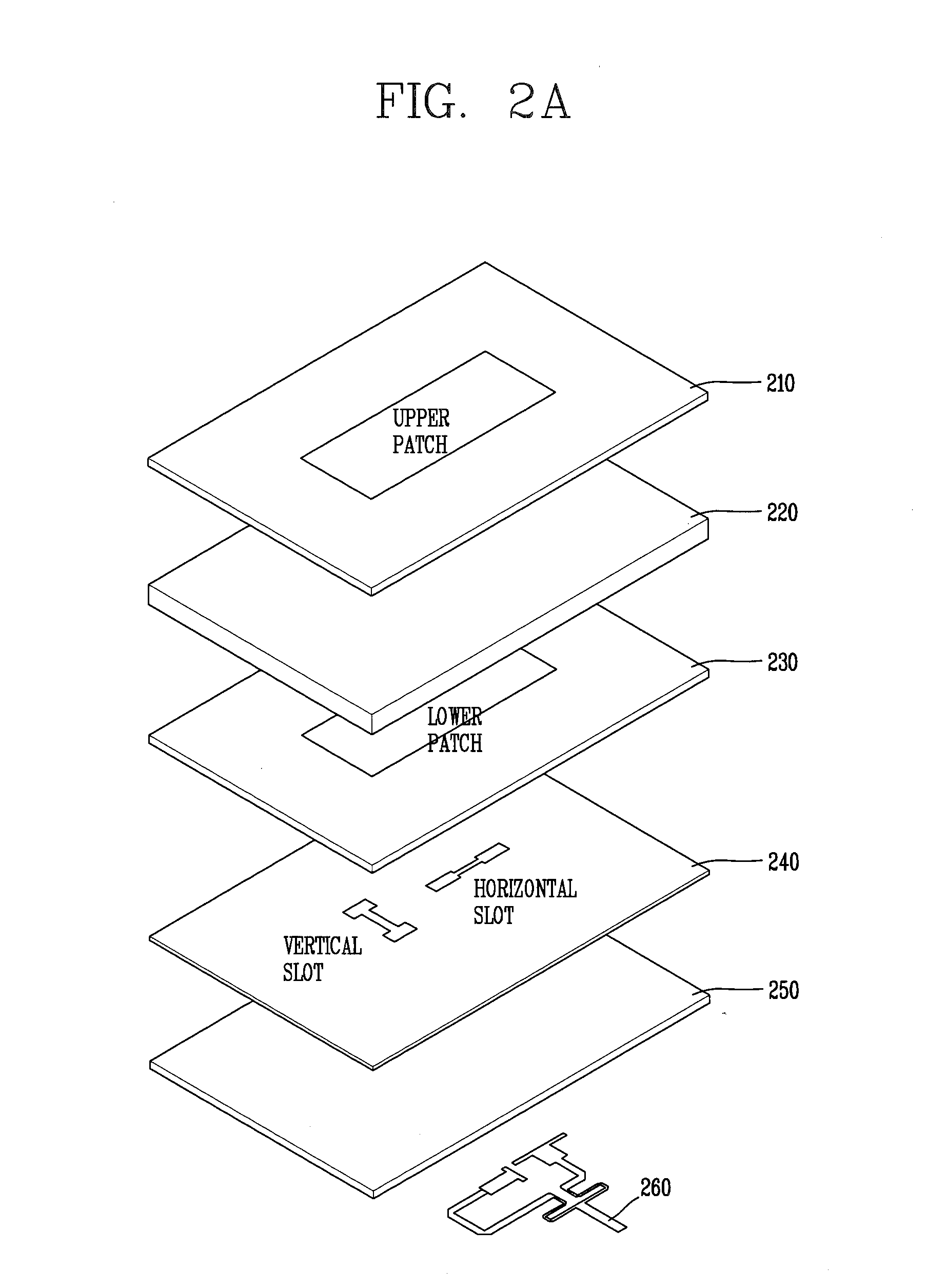
A rectenna according to the present invention includes a circular-polarized patch antenna having dual slots fed by a microstrip and configured to receive and output a radio frequency (RF) signal, and a rectifying circuit configured to convert for output the RF signal, received by the circular-polarized patch antenna, into a direct current (DC) signal and transfer the DC signal from the antenna to a load, wherein the rectifying circuit comprises at least one radial stub.

Description

CROSS-REFERENCE TO RELATED APPLICATION[0001]Pursuant to 35 U.S.C. §119(a), this application claims the benefit of earlier filing date and right of priority to Korean Application No. 10-2014-0128530, filed on Sep. 25, 2014, the contents of which is incorporated by reference herein in its entirety.BACKGROUND OF THE DISCLOSURE[0002]1. Field of the Disclosure[0003]This specification relates to a rectenna, and more particularly, a wideband rectenna.[0004]2. Background of the Disclosure[0005]A rectenna, which converts radio frequency (RF) energy to direct-current (DC) power, is a key component of free-space microwave power transmission (MPT) systems for the application of microwave powered unmanned aerial vehicle (UAVs), space solar power satellite stations (SSPS) and the like. The constraints on the design of MPT systems are the choice of an operating frequency and a system configuration of a transmitter and a receiver.[0006]Recently, an MPT consisting of an active phased array, a recten...

Claims


Application Information

Patent Timeline
IPC IPC(8): H01Q9/04H02J5/00
CPCH01Q9/0407H02J17/00H01Q9/0414H01Q9/0435H01Q9/0457H01Q5/378H01Q1/248H02J50/27H02J50/005H01P1/203H01Q13/08
Inventor SHIN, JIN, WOOCHOI, JUN, HOSO, JOON, HO
Owner AGENCY FOR DEFENSE DEV
Why Eureka
Try Eureka