Synchronous Machine With Common Motor/Generator Exciter Stage

a technology of exciter stage and synchronous machine, which is applied in the direction of synchronous generator control, synchronous motor, manufacturing stator/rotor body, etc., can solve the problems of synchronous machine, more complicated system in which it is being used, less reliable, and more complicated

Active Publication Date: 2016-03-31
THE BOEING CO
View PDF18 Cites 8 Cited by
  • Summary
  • Abstract
  • Description
  • Claims
  • Application Information

AI Technical Summary

Benefits of technology

[0003]A synchronous machine is disclosed which is operable as either a synchronous motor or a synchronous generator. The synchronous machine has a frame, a shaft, a main section, and an exciter section. The main section has a stator (a stationary winding, which may be an armature winding) which is mounted on the frame, and a rotor (a rotating winding, which may be a field winding) which is mounted on the shaft, the stator and the rotor being magnetically coupled to each other. The exciter section has a transformer and a rectifier. The transformer has a primary winding secured to the frame and a secondary winding secured to the shaft. The primary and secondary windings are spaced apart from, and magnetically coupled to, each other. The rectifier is electrically connected to the secondary winding, is mechanically connected to the rotor, and rectifies an output of the secondary winding to provide a rectified output to the rotor. The primary winding and the secondary winding of the transformer are each in the shape of a disk.

Problems solved by technology

The use of two exciter field windings and two control units make the synchronous machine and the system in which it is being used more complicated, heavier, and less reliable.
Dual field windings, dual control units, and / or switches and / or contactors add cost, weight, volume, and complexity to the system, and adversely affect the overall reliability of the system.
These large field windings substantially increase the amount and weight of the expensive copper used in the windings.
Further, with the conventional low frequency excitation current, the back electromotive force generated in the field windings is significantly affected by the rotor speed, and this can cause stability problems during the startup process.

Method used


Image

  • Synchronous Machine With Common Motor/Generator Exciter Stage
  • Synchronous Machine With Common Motor/Generator Exciter Stage
  • Synchronous Machine With Common Motor/Generator Exciter Stage

Examples


Embodiment Construction

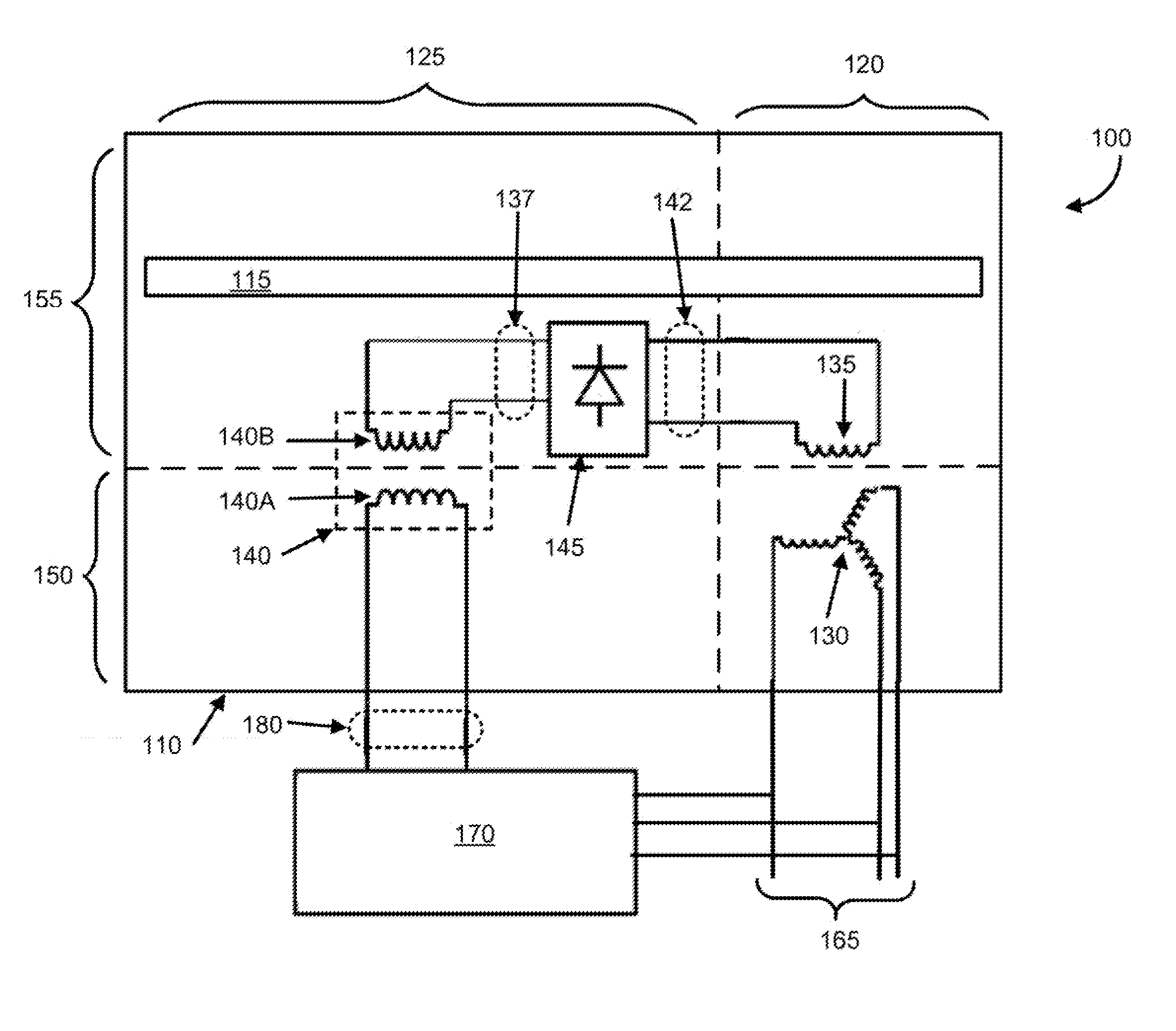
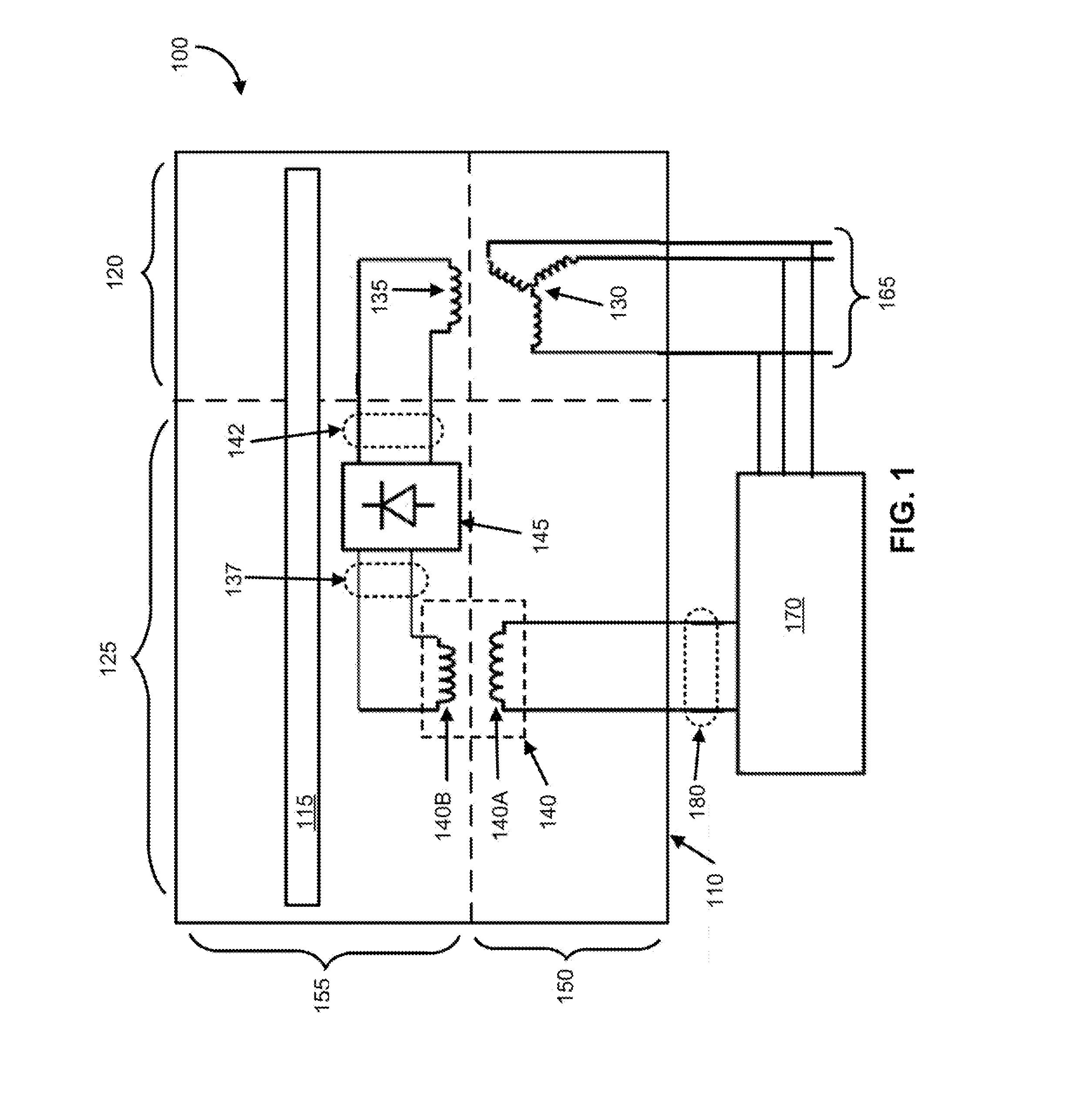
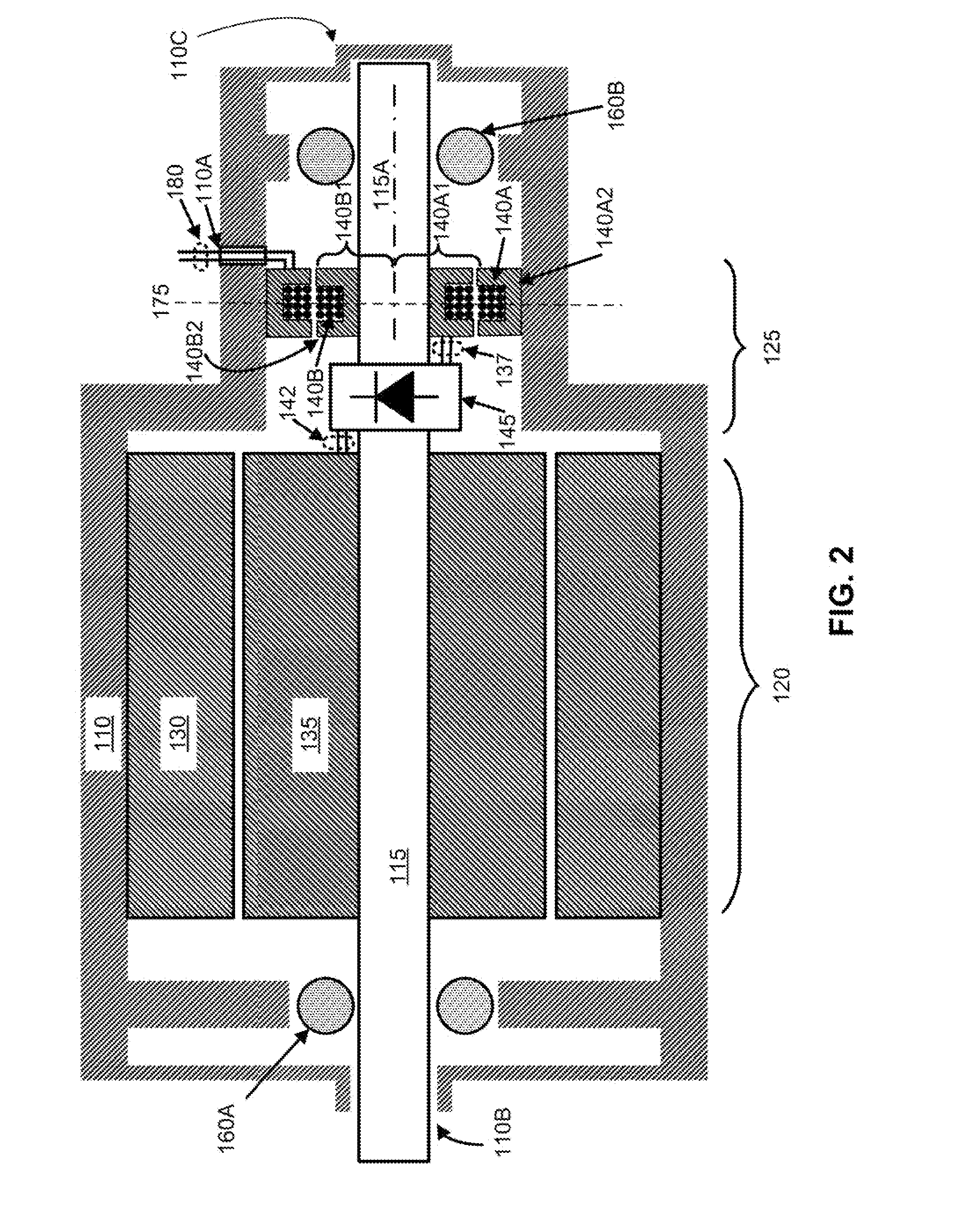
[0011]FIG. 1 is a diagram of an exemplary synchronous machine 100. The synchronous machine 100 has a frame 110, a shaft 115, a main section 120, and an exciter section 125. The main section 120 has a stator 130 (a stationary winding, which may be an armature winding) which is mounted on the frame, and a rotor 135 (a rotating winding, which may be a field winding) which is mounted on the shaft 115. Part of or all of the frame 110 may be part of, or may be distinct from, a casing which encloses the synchronous machine 100.

[0012]The exciter section 125 has a transformer 140 and a rectifier 145. The transformer 140 has a primary winding 140A mounted on the frame 110 and a secondary winding 140B mounted on the shaft 115. The secondary winding 140B is spaced apart from, and is magnetically coupled to, the primary winding 140A. The rectifier 145 is electrically connected by a plurality of electrical conductors 137 to the secondary winding 140B, is electrically connected by a plurality of e...


PUM


Abstract

A synchronous machine (100) has a frame (110), a shaft (115), a main section (120), and an exciter section (125). The main section (120) has a stator winding (130) which is mounted on the frame, and a rotor winding (135) which is mounted on the shaft. The exciter section has a transformer (140) and a rectifier (145). The transformer has a primary winding (140A) mounted on the frame and a secondary winding (140B) mounted on the shaft. The rectifier is mounted on the shaft and rectifies an output of the secondary winding to provide a rectified output to the rotor. A control unit (170) provides a high-frequency control signal to the primary winding. This signal is magnetically coupled to the secondary winding, rectified, and then applied to the rotor to control the operation of the synchronous machine.

Description

BACKGROUND[0001]A synchronous machine is an electric machine which can be operated as either a synchronous motor (synchronous motor mode) or a synchronous generator (synchronous generator mode). Conventionally, a synchronous machine has two separate and independent exciter field windings. Also, conventionally, two separate and independent control units have been used, one control unit for the exciter field winding for the synchronous motor mode and another control unit for the exciter field winding for the synchronous generator mode. The use of two exciter field windings and two control units make the synchronous machine and the system in which it is being used more complicated, heavier, and less reliable. The dual excitation components of a conventional synchronous machine may represent 20 to 30% of the total volume and weight of the synchronous machine. Some conventional systems use only a single, reconfigurable field winding, but still use two separate and independent control uni...

Claims


Application Information

Patent Timeline
Patent Type & Authority Applications(United States)
IPC IPC(8): H02K19/38H02K3/28H02K11/04H02K15/06
CPCH02K19/38H02K15/062H02K3/28H02K11/042H02K19/12H02K19/28H02K11/0094H02P9/02H02P2103/20H02P31/00
Inventor GAO, LIJUNKROLAK, MATTHEW, J.LIU, SHENGYI
Owner THE BOEING CO
Why Eureka
Try Eureka