Dynamically adjusting load balancing

a load balancing and dynamic adjustment technology, applied in the field of dynamic adjustment load balancing, can solve the problems of reducing the number of computing devices that receive load balancing traffic, unable to seamlessly grow, etc., and achieve the effect of reducing the load on this dcn, facilitating dlb operations, and increasing load

Active Publication Date: 2016-03-31
NICIRA
View PDF22 Cites 188 Cited by
  • Summary
  • Abstract
  • Description
  • Claims
  • Application Information

AI Technical Summary

Benefits of technology

[0009]A set of one or more controllers facilitate the DLB operations of some embodiments. For instance, in some embodiments, the load balancers on the hosts collect data traffic statistics based on the data messages that they load balance. These load balancers then pass the collected statistics to the controller set, which aggregates the statistics. In some embodiments, the controller set then distributes the aggregated statistics to load balancing agents that execute on the hosts. These agents then analyze the aggregated statistics to generate and/or to adjust load balancing criteria that the load balancers (that execute on the same hosts as the agents) enforce. In other embodiments, the controller set analyzes the aggregated statistics to generate and/or to adjust load balancing criteria, which the controller set then distributes to the hosts for their load balancers to enforce. In still other embodiments, the controller set generates

Problems solved by technology

These deployments also do not seamlessly grow and shrink the number of the computing dev

Method used


Image

  • Dynamically adjusting load balancing
  • Dynamically adjusting load balancing
  • Dynamically adjusting load balancing

Examples


Embodiment Construction

[0029]In the following detailed description of the invention, numerous details, examples, and embodiments of the invention are set forth and described. However, it will be clear and apparent to one skilled in the art that the invention is not limited to the embodiments set forth and that the invention may be practiced without some of the specific details and examples discussed.

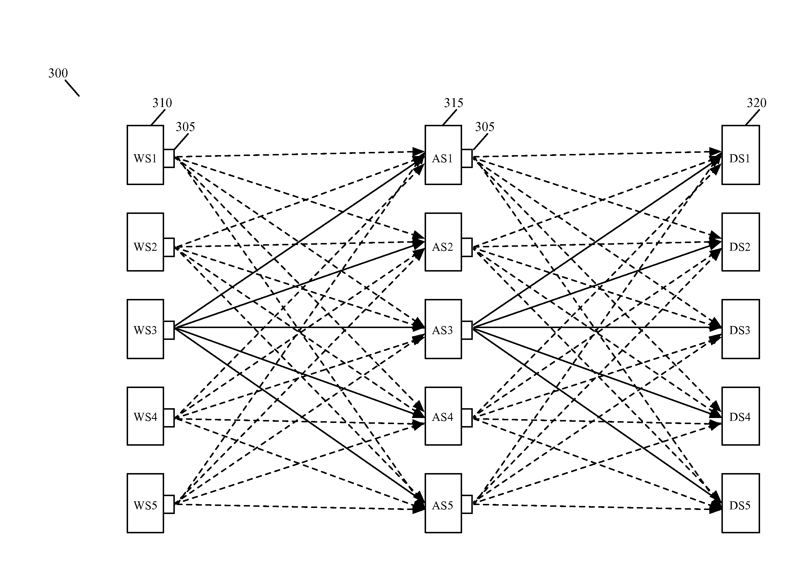
[0030]Some embodiments provide a novel method for load balancing data messages that are sent by a source compute node (SCN) to one or more different groups of destination compute nodes (DCNs). In some embodiments, the method deploys a load balancer in the source compute node's egress datapath. This load balancer receives each data message sent from the source compute node, and determines whether the data message is addressed to one of the DCN groups for which the load balancer spreads the data traffic to balance the load across (e.g., data traffic directed to) the DCNs in the group. When the received data mess...


PUM


Abstract

Some embodiments provide a novel method for load balancing data messages that are sent by a source compute node (SCN) to one or more different groups of destination compute nodes (DCNs). In some embodiments, the method deploys a load balancer in the source compute node's egress datapath. This load balancer receives each data message sent from the source compute node, and determines whether the data message is addressed to one of the DCN groups for which the load balancer spreads the data traffic to balance the load across (e.g., data traffic directed to) the DCNs in the group. When the received data message is not addressed to one of the load balanced DCN groups, the load balancer forwards the received data message to its addressed destination. On the other hand, when the received data message is addressed to one of load balancer's DCN groups, the load balancer identifies a DCN in the addressed DCN group that should receive the data message, and directs the data message to the identified DCN. To direct the data message to the identified DCN, the load balancer in some embodiments changes the destination address (e.g., the destination IP address, destination port, destination MAC address, etc.) in the data message from the address of the identified DCN group to the address (e.g., the destination IP address) of the identified DCN.

Description

BACKGROUND[0001]Load balancers are commonly used in datacenters to spread the traffic load to a number of available computing resources that can handle a particular type of traffic. FIGS. 1 and 2 illustrate two common deployments of load balancers in datacenters today. In FIG. 1, the load balancers 100 are topologically deployed at the edge of the network and between different types of VMs (e.g., between webservers 105 and application servers 110, and between application servers 110 and the database servers 115). The load balancers 100 are in some deployments standalone machines (e.g., F5 machines) that perform load balancing functions. Also, in some deployments, the load balancers are service virtual machines (VMs) that are executing on the same host computing devices that execute the different layers of servers that have their traffic balanced by the load balancers. FIG. 2 illustrates one such deployment of load balancers as service VMs (SVMs).[0002]In the load balancer deployment...

Claims


Application Information

Patent Timeline
IPC IPC(8): H04L45/24H04L45/74
CPCH04L67/1025H04L67/1029H04L67/1017H04L47/70H04L61/2521H04L45/24H04L47/125G06F9/45558G06F2009/4557H04L61/5069H04L2101/622H04L67/1001H04L45/44
Inventor JAIN, JAYANTSENGUPTA, ANIRBANPARTHASARATHY, MOHANSEQUEIRA, ALLWYNMASKALIK, SERGELUND, RICK
Owner NICIRA
Why Eureka
Try Eureka