Cooled component

Active Publication Date: 2016-04-07
ROLLS ROYCE PLC
View PDF2 Cites 33 Cited by
  • Summary
  • Abstract
  • Description
  • Claims
  • Application Information

AI Technical Summary

Benefits of technology

The present invention provides a cooled component with improved cooling efficiency. The component has a wall with effusion cooling apertures that have a metering portion and a diffusing portion. The metering portion has an elongated shape with a curved upstream end wall, a curved downstream end wall, and curved side walls. The effusion cooling apertures are arranged in longitudinally spaced rows and are offset laterally from adjacent rows. The ratio of the width of the metering portion to the length of the metering portion is between 3 and 1 to 8 to 1. The invention also provides a cooled component with a second wall having a plurality of impingement cooling apertures extending there-through from the third surface to the fourth surface. The cooling effect of the invention is achieved by improving the cooling efficiency of the cooled component.

Problems solved by technology

This causes the jets of coolant exiting the cylindrical effusion cooling apertures to detach from the surface of the component and results in a poor film of coolant on the surface of the component.
The high velocity of the jets of coolant also increases the mixing between the coolant and the hot fluid flowing over, or a hot fluid adjacent to, the surface of the component and this raises the temperature of the film of coolant and therefore reduces its cooling effect.
Additionally there may be relatively large distances between adjacent effusion cooling apertures and this may result in a film of coolant which is non-uniform across the surface of the component and hence there may be hot spots on the surface of the component between effusion cooling apertures.
However, it is expensive and time consuming to drill a large number of effusion cooling apertures using conventional manufacturing techniques, e.g. laser drilling, electro-chemical machining or electro-discharge machining.
The use of fanned effusion cooling apertures provides enhanced film cooling effectiveness, but fanned effusion cooling apertures have un-aerodynamic diffusion which suffers from flow separation and reduces its cooling effect.

Method used


Image

  • Cooled component
  • Cooled component
  • Cooled component

Examples


Embodiment Construction

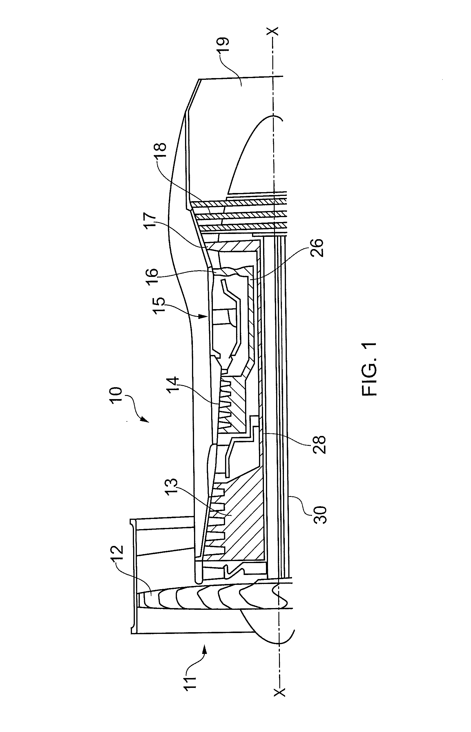
[0064]A turbofan gas turbine engine 10, as shown in FIG. 1, comprises in flow series an intake 11, a fan 12, an intermediate pressure compressor 13, a high pressure compressor 14, a combustion chamber 15, a high pressure turbine 16, an intermediate pressure turbine 17, a low pressure turbine 18 and an exhaust 19. The high pressure turbine 16 is arranged to drive the high pressure compressor 14 via a first shaft 26. The intermediate pressure turbine 17 is arranged to drive the intermediate pressure compressor 13 via a second shaft 28 and the low pressure turbine 18 is arranged to drive the fan 12 via a third shaft 30. In operation air flows into the intake 11 and is compressed by the fan 12. A first portion of the air flows through, and is compressed by, the intermediate pressure compressor 13 and the high pressure compressor 14 and is supplied to the combustion chamber 15. Fuel is injected into the combustion chamber 15 and is burnt in the air to produce hot exhaust gases which flow...


PUM


Abstract

A cooled gas turbine engine component comprises a wall which has a plurality of effusion cooling apertures extending there-through from a first surface to a second surface. Each aperture has an inlet in the first surface and an outlet in the second surface. Each aperture has a metering portion and a diffusing portion arranged in flow series and each metering portion is elongate and the width is greater than the length of the metering portion. The metering portion of each aperture has a U-shaped bend. The diffusing portion of each aperture is arranged at an angle to the second surface. Each outlet has a rectangular shape in the second surface of the wall. Each inlet has an elongate shape in the first surface of the wall and the inlet in the wall is arranged substantially diagonally with respect to the outlet in the wall.

Description

FIELD OF THE INVENTION[0001]The present invention relates to a cooled component and in particular to a cooled component of gas turbine engine.BACKGROUND TO THE INVENTION[0002]Components, for example turbine blades, turbine vanes, combustion chamber walls, of gas turbine engines and other turbomachines are cooled to maintain the component at a temperature where the material properties of the component are not adversely affected and the working life and the integrity of the component is maintained.[0003]One method of cooling components, turbine blades, turbine vanes combustion chamber walls, of gas turbine engines provides a film of coolant on an outer surface of a wall of the component. The film of coolant is provided on the outer surface of the wall of the component by a plurality of effusion cooling apertures which are either arranged perpendicular to the outer surface of the wall or at an angle to the outer surface of the wall. The effusion apertures are generally manufactured by ...

Claims


Application Information

Patent Timeline
IPC IPC(8): F01D5/18F01D9/06F23R3/00
CPCF01D5/186F01D9/065F23R3/005F23R3/002F05D2240/81F05D2260/202F23R2900/03041F23R2900/03042F23R2900/03044
Inventor HARDING, STEPHEN C.HUCKER, PAUL A.WORTH, NICHOLAS
Owner ROLLS ROYCE PLC
Why Eureka
Try Eureka