Skew managed multi-core optical fiber interconnects

a multi-core, optical fiber technology, applied in the direction of cladded optical fibre, instruments, optical elements, etc., can solve the problems of multi-core optical fiber crosstalk between cores of fiber, significant increase in fiber manufacturing cost, capacity scaling, compactness,

Active Publication Date: 2016-04-07
CORNING INC
View PDF10 Cites 42 Cited by
  • Summary
  • Abstract
  • Description
  • Claims
  • Application Information

AI Technical Summary

Benefits of technology

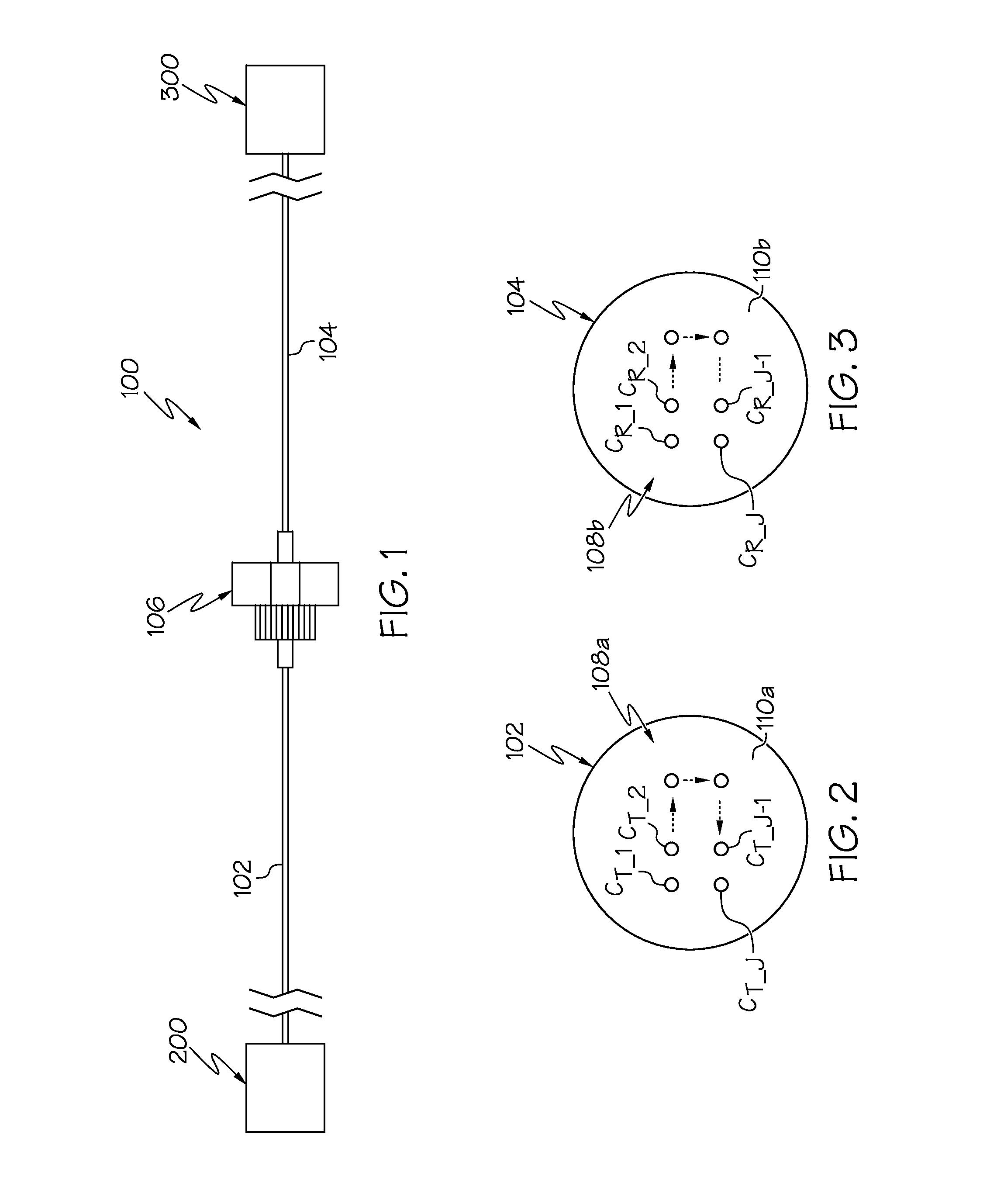
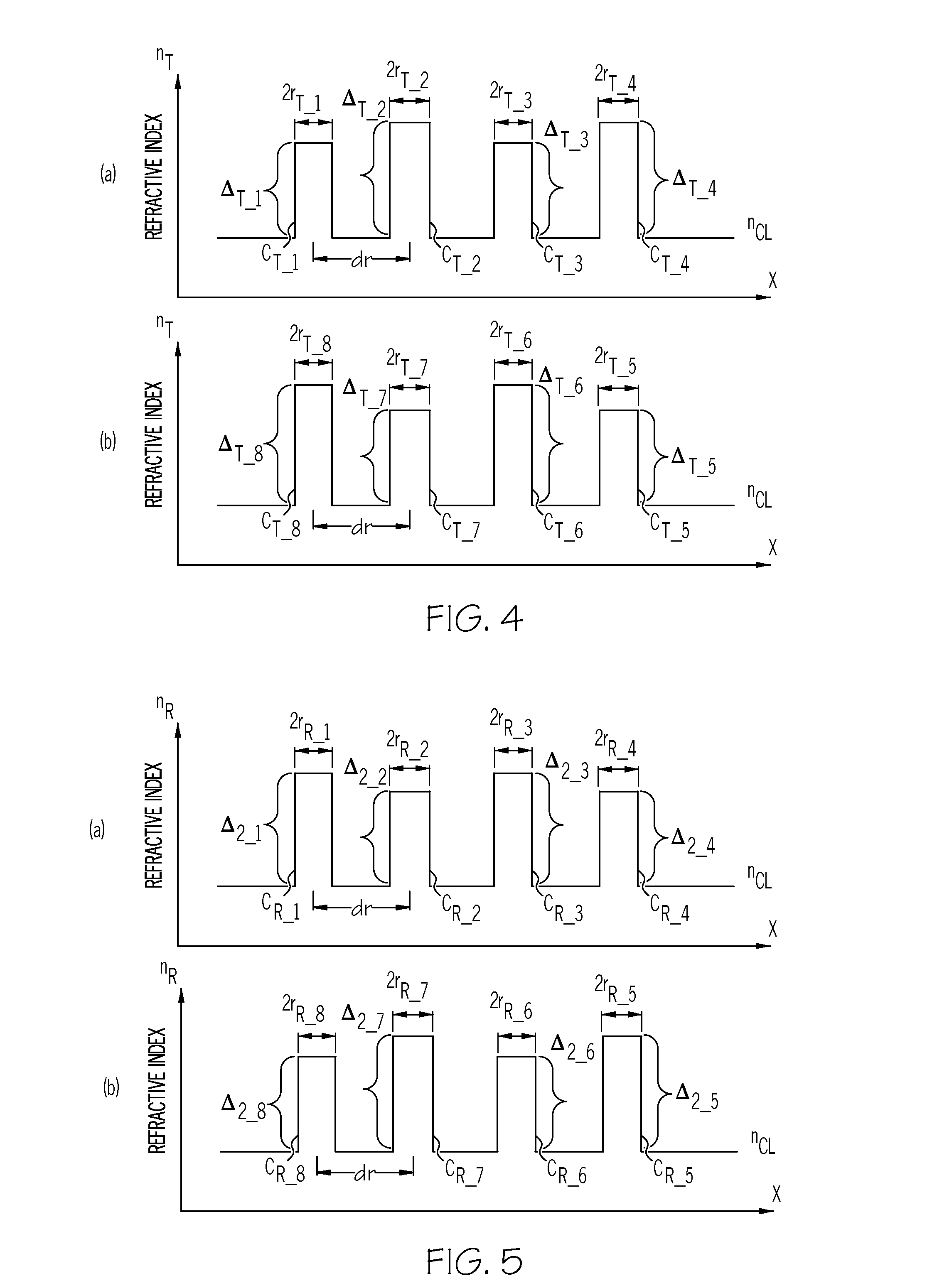
[0008]According to one embodiment, a multi-core optical fiber interconnect includes a transmitting multi-core optical fiber having a length LT. The multi-core optical fiber interconnect may also include a first transmitting core element CT_1 positioned in a first common outer cladding, the first transmitting core element CT_1 having a group refractive index nT_1g and an effective refractive index neffT_1. The transmitting mulit-core optical fiber may also include a second transmitting core element CT_2 positioned in the first common outer cladding adjacent to the first transmitting core element CT_1, the second transmitting core element CT_2 having a group refractive index nT_2g and an effective refractive index neffT_2, wherein neffT_1 and neffT_2 are different. The multi-core optical fiber interconnect may also include a receiving multi-core optical fiber comprising having a length LR. The receiving multi-core optical fiber may have a first receiving core element CR_1 positioned in a second common outer cladding, the first receiving core element CR_1 having a group refractive index nR_1g and an effective refractive index neffR_1. The receiving multi-core optical fiber may also include a second receiving core element CR_2 positioned in the second common outer cladding adjacent to the first receiving core element CR_1, the second receiving core element CR_2 having a group refractive index nR_2g and an effective refractive index neffR_2, wherein neffR_1 and neffR_2 are different. The first transmitting core element CT_1 may be optically coupled to the first receiving core element CR_1 and the second transmitting core element CT_2 may be optically coupled to the second receiving core element CR_2. The length LT of the transmitting multi-core optical fiber, the length LR of the receiving multi-core optical fiber, and the group refractive indexes of the each of the core elements satisfy the relation (nT_1gLT+nR_1gLR)=(nT_2gLT+nR_2gLR).

Problems solved by technology

One drawback of multi-core optical fibers is crosstalk between cores in the fiber.
A requirement of low total crosstalk in interconnects limits the density of cores within the multi-core optical fiber, and thus the capacity scaling, compactness, and cost of the interconnect formed from the multi-core optical fiber.
However, one issue of introducing a trench associated with each core is the significant increase in fiber manufacturing cost.
However, the different propagating constants between the two cores produces large optical signal time delays between the cores, otherwise referred to as skew.
This unwanted skew increases the difficulty of implementing crosstalk equalizers in a communication system.

Method used


Image

  • Skew managed multi-core optical fiber interconnects
  • Skew managed multi-core optical fiber interconnects
  • Skew managed multi-core optical fiber interconnects

Examples


example 1

[0085]Table 1 below contains six design examples (D1-D6) of single-moded core elements which may be used for either the transmitting multi-core optical fiber or the receiving multi-core optical fiber of a multi-core optical fiber interconnect. Example D1 is similar to a standard single mode fiber core design. The fiber is single-moded at both 1310 and 1550 nm wavelength windows. Example D2 has a higher core delta and smaller core radius than a typical single-moded core element and the mode field diameters (MFDs) are smaller than those of standard single-mode optical fiber core elements. Example D3 has an increased core radius which has the effect of increasing the MFDs of the core element. However, the cutoff wavelength of the LP11 mode is higher than 1310 nm so the fiber is single-moded at only the 1550 nm windows. Example D4 has a graded-index refractive index profile with α=2. Examples D5 and D6 have step-index refractive index profiles which are surrounded by a low-index annulus...

example 2

[0086]Table 2 below contains six examples of core pairings which may be used to form interconnect core elements of a multi-core optical fiber interconnect, specifically referring to the Examples D1-D6 from Table 1 above. In these examples, Core I may be a transmitting optical fiber core element CT_j of the transmitting multi-core optical fiber and Core II may be a receiving optical fiber core element CR_j of the receiving multi-core optical fiber. Alternatively, Core II may be a transmitting optical fiber core element CT_j of the transmitting multi-core optical fiber and Core I may be a receiving optical fiber core element CR_j of the receiving multi-core optical fiber. As shown in Table 2, the effective index difference between the two cores in each pairing is greater than 0.2×10⁻⁴, which is sufficient to reduce the crosstalk between adjacent interconnect core elements. In addition, the spacing dr between adjacent core elements is greater than or equal to 25 um to further mitigate ...


PUM


Abstract

The embodiments described herein relate to multi-core optical fiber interconnects which include at least two multi-core optical fibers. The multi-core optical fibers are connected such that the core elements of the first multi-core optical fiber are optically coupled to the core elements of the second multi-core optical fiber thereby forming an array of interconnect core elements extending through the optical fiber interconnect. The multi-core optical fibers are constructed such that cross-talk between adjacent core elements in each multi-core optical fiber are minimized. The multi-core optical fibers are also constructed such that time-delays between the interconnect core elements in the array of interconnect core elements are also minimized.

Description

[0001]This application claims the benefit of priority under 35 U.S.C. §119 of U.S. Provisional Application Ser. No. 62 / 060,064 filed on Oct. 6, 2014 the content of which is relied upon and incorporated herein by reference in its entirety.BACKGROUND[0002]1. Field[0003]The present specification generally relates to optical fiber interconnects and, more specifically, to multi-core optical fiber interconnects with reduced optical signal time delays between core elements within the transmission interconnects.[0004]2. Technical Background[0005]In recent years optical fiber has become accepted as a viable alternative to traditional materials used for data signal communication. Optical fiber is now widely utilized in a variety of electronic devices to facilitate the high-speed communication of data signals at high bandwidths. However, as the speed and bandwidth of the electronic components in data communication devices increases, there is a corresponding need to increase the speed of optica...

Claims


Application Information

Patent Timeline
Patent Type & Authority Applications(United States)
IPC IPC(8): G02B6/38G02B6/028G02B6/02
CPCG02B6/38G02B6/028G02B6/02042G02B6/0281G02B6/0365G02B6/255G02B6/43
Inventor LI, MING-JUNLI, SHENPING
Owner CORNING INC
Why Eureka
Try Eureka