Fluid drainage container

a technology of fluid drainage container and fluid, which is applied in the direction of suction drainage container, intravenous device, other medical devices, etc., can solve the problems of high manufacturing cost and inability to easily adjust the volume of the container

Active Publication Date: 2016-04-21
XPELLA PTY LTD
View PDF19 Cites 7 Cited by
  • Summary
  • Abstract
  • Description
  • Claims
  • Application Information

AI Technical Summary

Benefits of technology

[0006]The invention provides a fluid drainage device for use in a closed wound drainage system which includes a body with a cylindrical bore which defines at least part of a fluid-receiving volume, an inlet to the fluid-receiving volume, a piston in sealing contact with the bore which partly bounds the fluid-receiving volume inside the bore, the piston being movable between a first position and a second position, a piston rod which extends from the piston, an energy storage device engaged with the piston rod, a user-actuated handle mechanism which is movable relative to the body in a first direction, to allow the piston to move from the first position, whereby energy is stored in the energy storage device, to the second position, whereby energy is released from the energy storage device, thereby increasing the size of the fluid-receiving volume, reducing the pressure in the fluid-receiving volume and allowing fluid to flow from a suitable conduit through the inlet and into the fluid-receiving volume.

Problems solved by technology

Although these systems all drain fluid, they have varying degrees of efficacy and the manufacturing cost thereof can often be high.
Some devices are also specific to the volume of fluid to be drained and it is often not possible to adjust this volume easily to suit a particular patient's needs.

Method used


Image

  • Fluid drainage container
  • Fluid drainage container
  • Fluid drainage container

Examples


Embodiment Construction

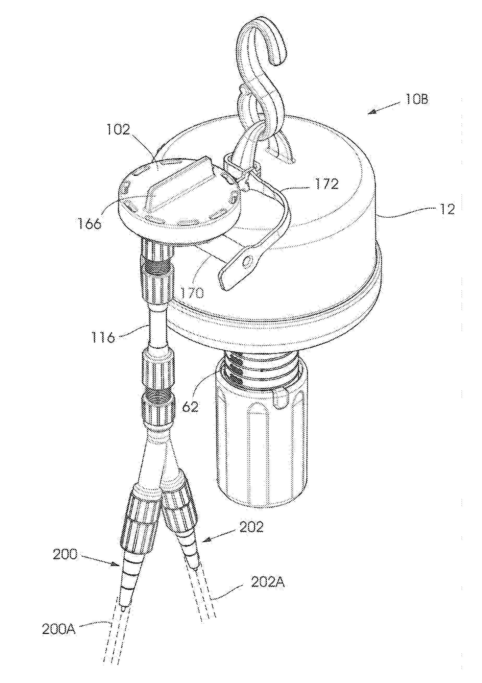
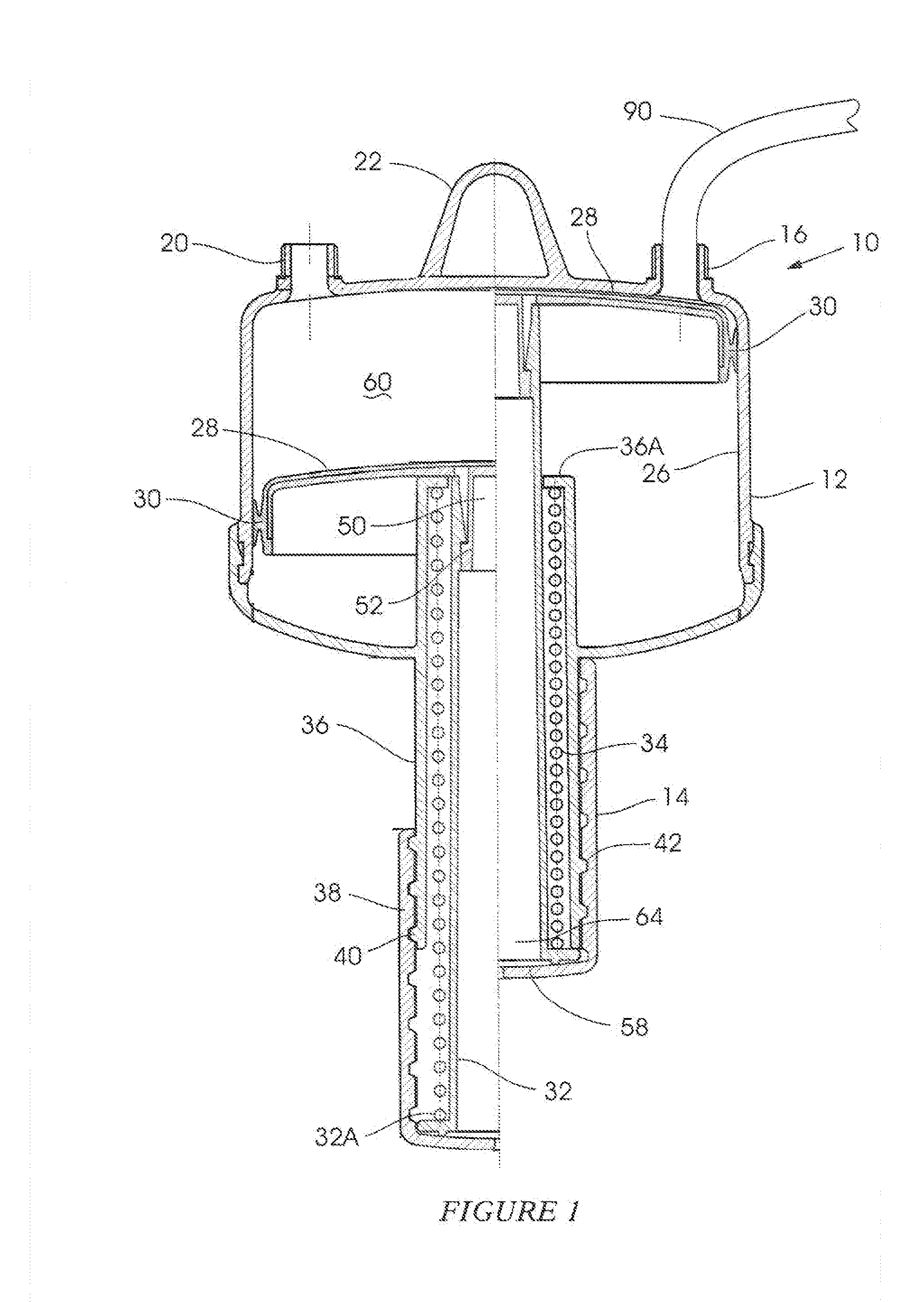
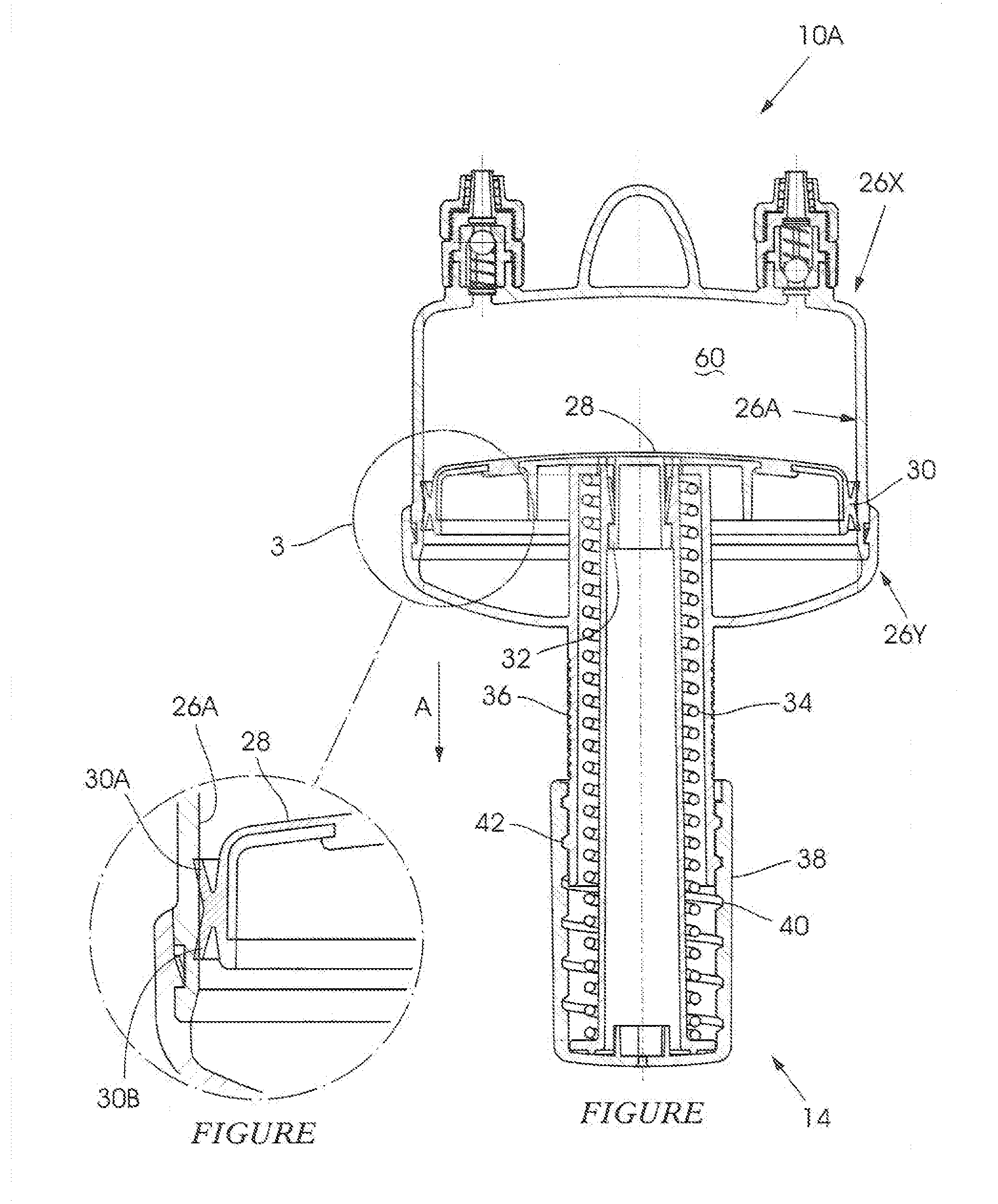
[0041]FIG. 1 of the accompanying drawings shows a device 10 for use a fluid drainage system. The device has a container body 12 and a user-actuable handle mechanism 14 at a lower end of the body. A fluid inlet 16 is positioned on one side of a lid 18. A fluid drainage outlet 20 is positioned on an opposing side of the lid.

[0042]A formation 22 which allows the container body 12 to be suspended from overhead structure, not shown, is centrally located on the lid.

[0043]The right and left ides of the drawing how the device 10 in cross section in different operative modes.

[0044]The body 12 is cylindrical in shape and, internally, defines a cylindrical bore 26 with a smooth internal surface. A piston 28, of complementary shape to the bore, is slidingly positioned inside the bore. The piston has an external seal 30 which ensures that an intimate seal established between the piston and the bore. A fluid-receiving volume 60 of variable size is defined by the position of the piston inside the ...


PUM


Abstract

A fluid drainage device, for use in a closed wound drainage system, which includes a fluid-receiving volume having a bore, a piston in sealing contact with the bore, a prop extending from the piston and which is connected to an energy storage device, wherein the piston can be user-actuated between a first position, whereby energy is stored in the energy storage device, to a second position, whereby energy is released from the energy storage device, to increase the size and reduce the pressure of the volume, allowing fluid to flow from a conduit into the volume.

Description

BACKGROUND OF THE INVENTION[0001]This invention relates to the drainage of body fluids from a closed wound.[0002]The draining of fluid from a closed wound, particularly after surgery, is beneficial as it promotes healing and removes a build-up of fluid which would other otherwise remain in the body and which would increase the chances of infection.[0003]Various drainage systems have been proposed most of which operate through the use of a partial vacuum in order to promote the drainage of fluids. These drainage systems are usually in the form of compressive containers, electric vacuum machines or pre-charged disposable containers.[0004]Although these systems all drain fluid, they have varying degrees of efficacy and the manufacturing cost thereof can often be high. In some devices, a vacuum is not always constantly applied and a user must constantly check and re-adjust the device to ensure that the fluid is being drained effectively. Typically, the vacuum level is higher at the star...

Claims


Application Information

Patent Timeline
Patent Type & Authority Applications(United States)
IPC IPC(8): A61M1/00
CPCA61M1/0031A61M2205/3337A61M1/0068A61M2205/073A61M1/63A61M1/67A61M1/74A61M1/918A61M1/81
Inventor SCHMITT, KARL-HEINZ
Owner XPELLA PTY LTD
Why Eureka
Try Eureka