Control, apparatus for autonomously navigating utility vehicle

Active Publication Date: 2016-04-21
HONDA MOTOR CO LTD
View PDF11 Cites 20 Cited by
  • Summary
  • Abstract
  • Description
  • Claims
  • Application Information

AI Technical Summary

Benefits of technology

[0013]The object of this invention is to overcome the aforesaid problems by providing a control apparatus for an autonomously navigating utility vehicle configured to

Problems solved by technology

A point of interest in this is that the magnetic field intensity generated by the boundary wire is inversely proportional to distance of the vehicle from the boundary wire, i.e., that the magnetic field intensity diminishes with increasing distance of the vehicle from the boundary wire, which makes accurate determination of the position with respect to a large working area difficult.
Moreover, noise picked up by the sensor includes periodically-generated noise similar to that generated by the vehicle itself, so that when a configurat

Method used


Image

  • Control, apparatus for autonomously navigating utility vehicle
  • Control, apparatus for autonomously navigating utility vehicle
  • Control, apparatus for autonomously navigating utility vehicle

Examples


Embodiment Construction

[0028]A control apparatus for an autonomously navigating utility vehicle according to an embodiment of this invention is explained with reference to the attached drawings in the following.

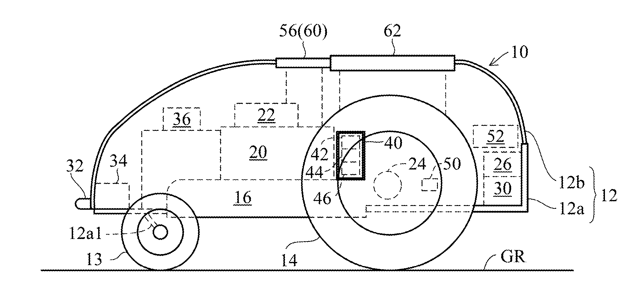
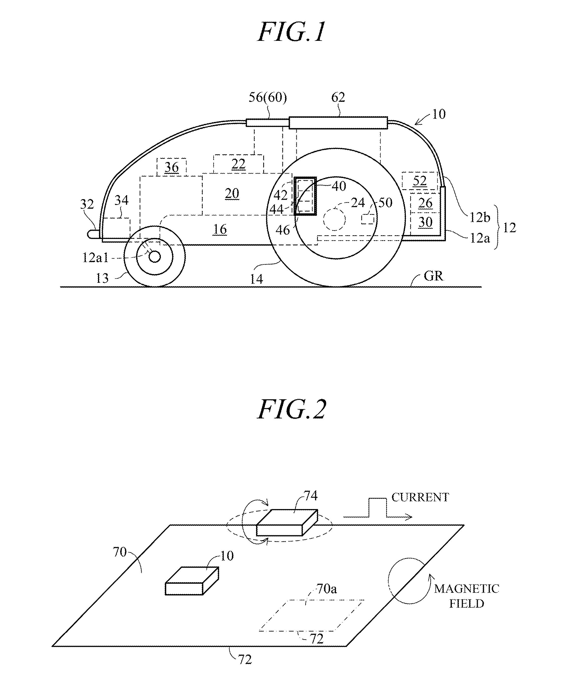
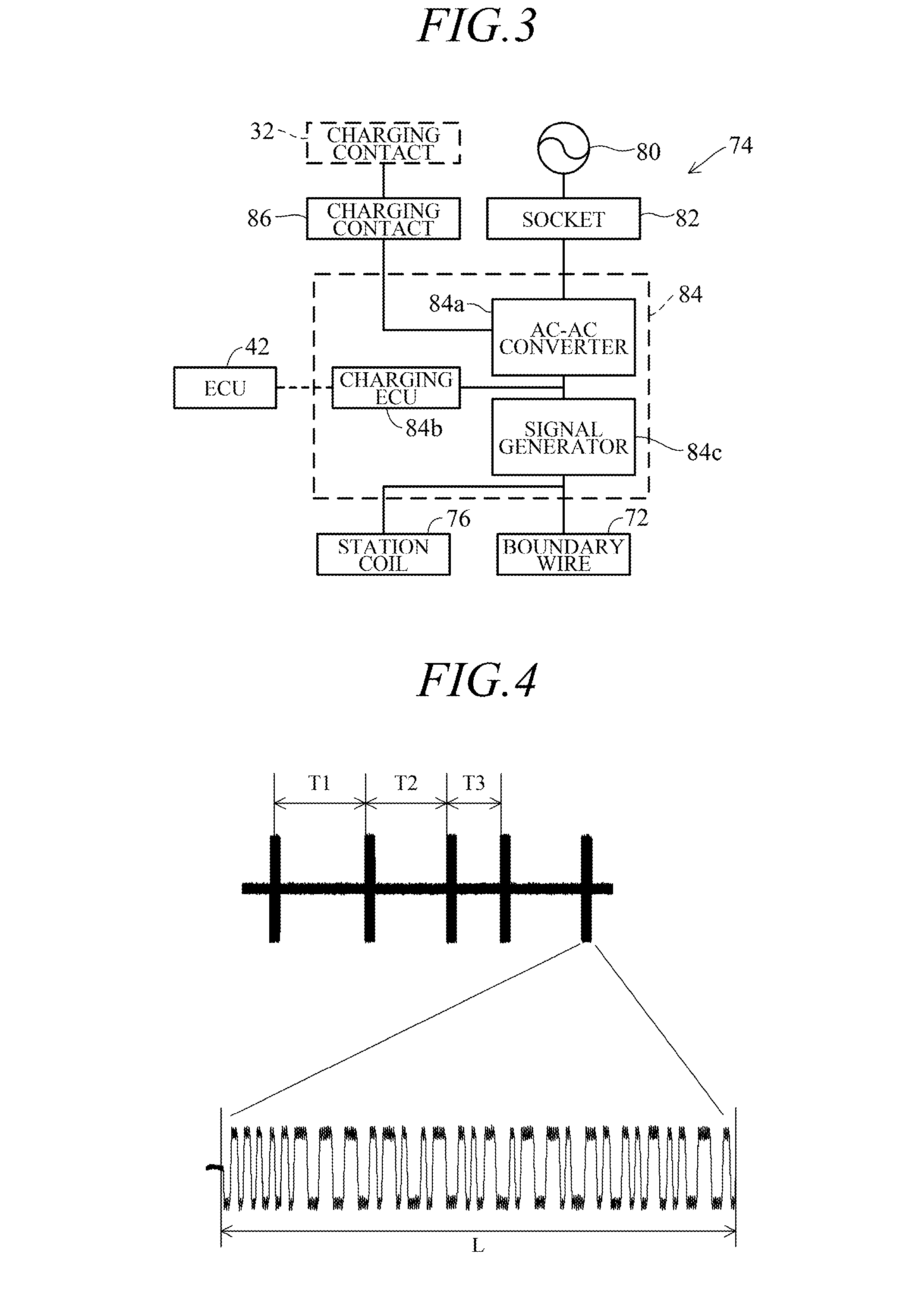
[0029]FIG. 1 is an overall schematic diagram showing a control apparatus for an autonomously navigating utility vehicle according to an embodiment of this invention, FIG. 2 is an explanatory diagram explaining work of the autonomously navigating utility vehicle controlled by the control apparatus shown in FIG. 1, and FIG. 3 is a block diagram showing configuration of a charging station of the autonomously navigating utility vehicle shown in FIG. 1 and a magnetic field generator. Elements shown in FIG. 1 is simplified in FIG. 2 for ease of brevity.

[0030]As shown in FIG. 1, reference symbol 10 designates an autonomously navigating utility vehicle, e.g., a mower; hereinafter called “vehicle”. A body 12 of the vehicle 10 comprises a chassis 12a and a frame 12b attached thereto. The vehicle 10 is equipp...


PUM


Abstract

In an apparatus for controlling operation of an autonomously navigating utility vehicle adapted to run about a working area defined by a boundary wire which generates magnetic field therearound when supplied with electric current and having a magnetic sensor that produces an output indicating intensity of magnetic field generated by the boundary wire and a position determining unit that determine a position of the vehicle with respect to the working area based on the output of the magnetic sensor, a coded data signal determined to be inherent to the working area is generated and supplied to the electric current, and the position determining unit detects the data signal and determines the position of the vehicle based on a rate of concordance of the detected data signal and a reference signal.

Description

CROSS-REFERENCE TO RELATED APPLICATION[0001]This application is based upon and claims the benefit of priority from Japanese Patent Application No. 2014-214783 filed on Oct. 21, 2014, the contents of which are incorporated herein by reference.BACKGROUND OF THE INVENTION[0002]1. Field of the Invention[0003]This invention relates to a control apparatus for an autonomously navigating utility vehicle, particularly to an apparatus, used in a utility vehicle that autonomously navigates and works in a working area, that controls operation of a work unit while determining a position (self-position) with respect to the working area.[0004]2. Description of Related Art[0005]Among prior art control apparatuses that determine a position of the autonomously navigating utility vehicle with respect to a working area in order to control operation of a work unit can be cited, for example, those taught by Patent Documents 1 and 2.[0006]A technical concept taught by Patent Document 1 (International Pate...

Claims


Application Information

Patent Timeline
IPC IPC(8): G01C21/20G01R33/02G05D1/00
CPCG01C21/20G01R33/02G05D1/0088G05D1/0265A01D34/008H03M5/12G05D2201/0208
Inventor EGUCHI, JUNICHIKAWAKAMI, TOSHIAKINISHIMURA, JINMURAKAMI, GEORGEOKADA, KOUICHI
Owner HONDA MOTOR CO LTD
Why Eureka
Try Eureka