Apparatus and method for improved signal fade out in different domains during error concealment

a signal fade out and error concealment technology, applied in the field of audio signal encoding, processing and decoding, can solve the problems of inability to use parameters close to one, inaccurate noise estimation, and inability to transit smoothly, so as to prolong the effect of prolonging the spectral shape of the last good fram

Active Publication Date: 2016-04-21
FRAUNHOFER GESELLSCHAFT ZUR FOERDERUNG DER ANGEWANDTEN FORSCHUNG EV
View PDF21 Cites 11 Cited by
  • Summary
  • Abstract
  • Description
  • Claims
  • Application Information

AI Technical Summary

Benefits of technology

[0225]Some of embodiments of the present invention provide a time varying smoothing parameter such that the tracking capabilities of the smoothed periodogram and its variance are better balanced, to develop an algorithm for bias compensation, and to speed up the noise tracking in general.
[0316]To overcome this, only the updated TCX LTP buffer may be fed back (without adding noise), in order to not pollute the tonal information with undesired random noise.

Problems solved by technology

It should be noted that the switching is performed instantly, it does not transit smoothly.
This will lead to inaccurate noise estimates as the sliding window for the minimum search might slip into broad peaks.
Thus, smoothing parameters close to one cannot be used, and, as a consequence, the noise estimate will have a relatively large variance.
There is no known technology, where a common noise level tracing is necessitated.
Tracing the level in the excitation domain, e.g., before the FDNS, would theoretically also be possible, but the level compensation between the TCX excitation domain and the ACELP excitation domain is deemed to be rather complex.
No known technology incorporates such a common background level tracing in different domains.
The known techniques do not have such a common comfort noise level tracing, e.g., in the excitation domain, in a switched codec system.
A drawback of the approach of the known technology to apply the attenuation factor in the frequency domain is that aliasing will be caused in the overlap-add region in the time domain.
This will be the case for adjacent frames to which different attenuation factors are applied, because the fading procedure causes the TDAC (time domain alias cancellation) to fail.
By this, the known techniques cause unwanted side effects, since the gain of the subsequent LPC synthesis depends on the signal characteristics, which are altered by this high pass filter.
This leads to a wrong output level even though the excitation level is correct.
This mismatch of the comfort noise characteristics might be disturbing.
This has the drawback that the short-term spectral shape is prolonged, leading frequently to a repetitive, metallic sound which is not background noise like, and thus cannot be used as comfort noise.
The drawback of this procedure of the known technology is, that for consecutively lost frames the same spectrum is used again and again, just with different sign randomizations and global attenuation.
Otherwise the outputted spectrum will never match the targeted envelope used for FDNS processing.
The tonal components are hence getting distorted more and more over time by the added noise.
Especially for clean speech or speech over background noise, it is extremely unlikely that a tone or harmonic will decay very slowly over a very long time.
Moreover, it is impossible to reach the comfort noise envelope during burst packet losses, if the TCX LTP is applied during the burst loss without being attenuated over time, because the signal will then incorporate the voicing information of the LTP.
A drawback of the known technology of not using the TCX LTP is, that all tonal components being modelled with the LTP disappear abruptly.
Moreover, in ACELP based codecs of the known technology, the LTP operation is prolonged during concealment, and the gain of the adaptive codebook is faded towards zero.

Method used


Image

  • Apparatus and method for improved signal fade out in different domains during error concealment
  • Apparatus and method for improved signal fade out in different domains during error concealment
  • Apparatus and method for improved signal fade out in different domains during error concealment

Examples


Embodiment Construction

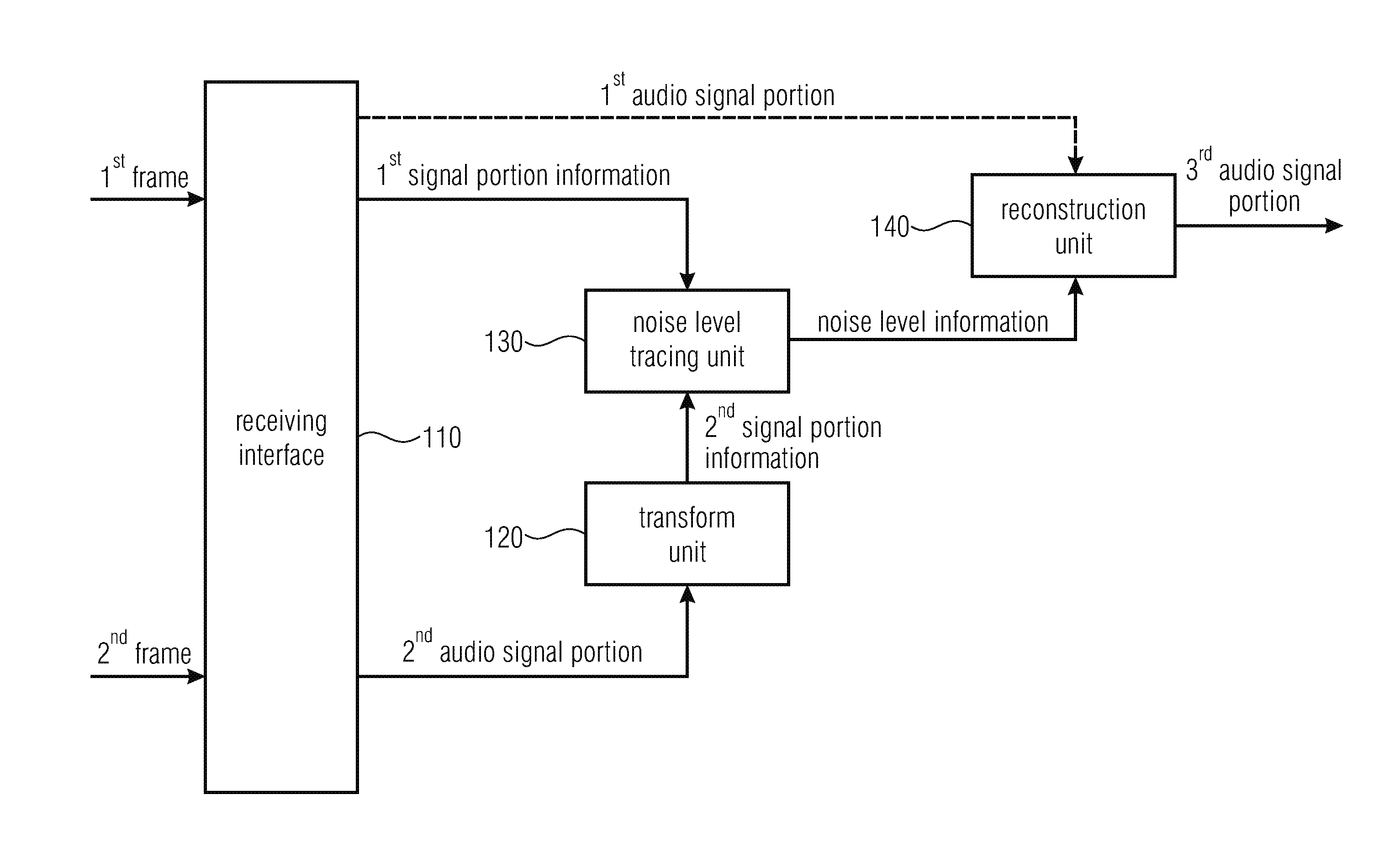
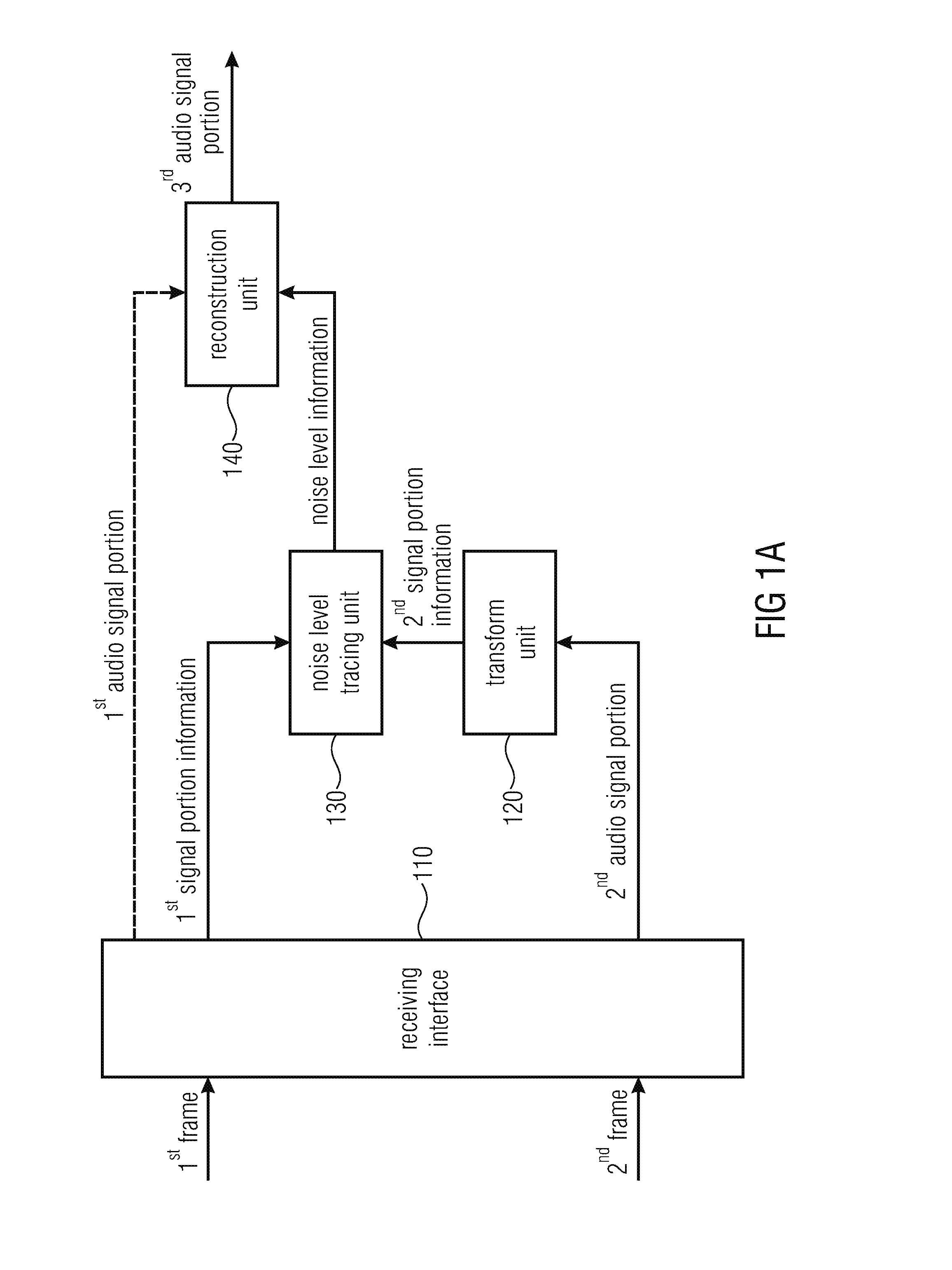
[0340]FIG. 1A illustrates an apparatus for decoding an audio signal according to an embodiment.

[0341]The apparatus comprises a receiving interface 110. The receiving interface is configured to receive a plurality of frames, wherein the receiving interface 110 is configured to receive a first frame of the plurality of frames, said first frame comprising a first audio signal portion of the audio signal, said first audio signal portion being represented in a first domain. Moreover, the receiving interface 110 is configured to receive a second frame of the plurality of frames, said second frame comprising a second audio signal portion of the audio signal.

[0342]Moreover, the apparatus comprises a transform unit 120 for transforming the second audio signal portion or a value or signal derived from the second audio signal portion from a second domain to a tracing domain to obtain a second signal portion information, wherein the second domain is different from the first domain, wherein the ...


PUM


Abstract

An apparatus for decoding an audio signal is provided, having a receiving interface, configured to receive a first frame having a first audio signal portion of the audio signal, and configured to receive a second frame having a second audio signal portion of the audio signal; a noise level tracing unit, wherein the noise level tracing unit is configured to determine noise level information depending on at least one of the first audio signal portion and the second audio signal portion; a first reconstruction unit for reconstructing, in a first reconstruction domain, a third audio signal portion of the audio signal depending on the noise level information; a transform unit for transforming the noise level information to a second reconstruction domain; and a second reconstruction unit for reconstructing, in the second reconstruction domain, a fourth audio signal portion of the audio signal depending on the noise level information.

Description

CROSS-REFERENCE TO RELATED APPLICATIONS[0001]This application is a continuation of copending International Application No. PCT / EP2014 / 063177, filed Jun. 23, 2014, which claims priority from European Application No. 13 173 154.9, filed Jun. 21, 2013, and from European Application No. 14 166 998.6, filed May 5, 2014, which are each incorporated herein in its entirety by this reference theretoBACKGROUND OF THE INVENTION[0002]The present invention relates to audio signal encoding, processing and decoding, and, in particular, to an apparatus and method for improved signal fade out for switched audio coding systems during error concealment.[0003]In the following, the state of the art is described regarding speech and audio codecs fade out during packet loss concealment (PLC). The explanations regarding the state of the art start with the ITU-T codecs of the G-series (G.718, G.719, G.722, G.722.1, G.729. G.729.1), are followed by the 3GPP codecs (AMR, AMR-WB, AMR-WB+) and one IETF codec (O...

Claims


Application Information

Patent Timeline
Patent Type & Authority Applications(United States)
IPC IPC(8): G10L19/005G10L19/22
CPCG10L19/22G10L19/005G10L19/0212G10L19/09G10L19/002G10L19/012G10L19/083H03M7/30G10L19/06G10L19/12G10L2019/0002G10L2019/0011G10L2019/0016G10L19/07
Inventor SCHNABEL, MICHAELGORAN, MARKOVICSPERSCHNEIDER, RALPHLECOMTE, JEREMIEHELMRICH, CHRISTIAN
Owner FRAUNHOFER GESELLSCHAFT ZUR FOERDERUNG DER ANGEWANDTEN FORSCHUNG EV
Why Eureka
Try Eureka