Separator and galvanic cell providing robust separation of anode and cathode

Active Publication Date: 2016-04-21
ROBERT BOSCH GMBH
View PDF6 Cites 13 Cited by
  • Summary
  • Abstract
  • Description
  • Claims
  • Application Information

AI Technical Summary

Benefits of technology

[0005]One objective of the present invention is to provide a separator and a galvanic cell whose structure is such that damage to individual components

Problems solved by technology

Apart from thermal runaway and a fire risk, there is the problem in lithium batteries that dent rides are formed, which not only reduces the performance of the lithium battery b

Method used


Image

  • Separator and galvanic cell providing robust separation of anode and cathode
  • Separator and galvanic cell providing robust separation of anode and cathode

Examples


Example

[0038]Identical or similar components are designated by the same or similar reference numerals in the following descriptions of the exemplary embodiments of the present invention, and a repeated description of these components is omitted in individual cases. The figures represent the subject matter of the present invention only schematically.

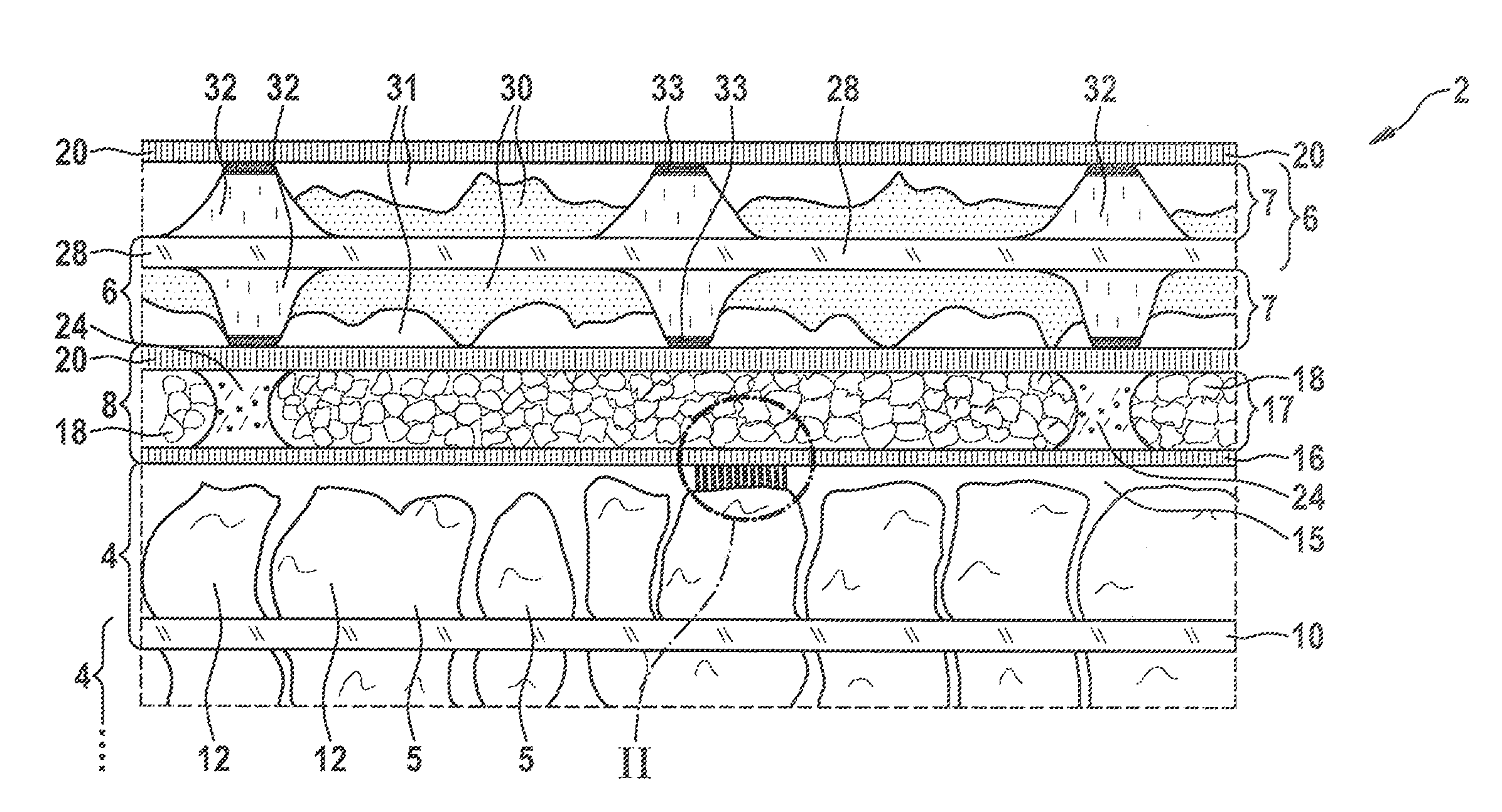
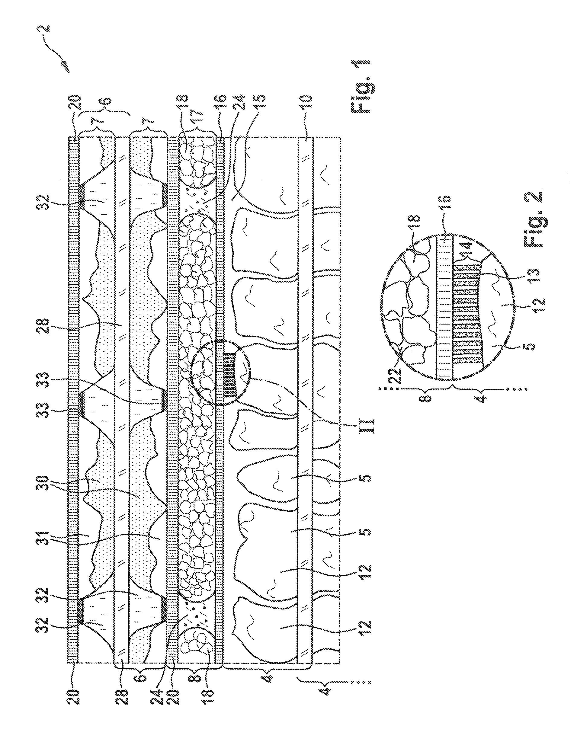
[0039]FIG. 1 shows a sectional side view of a galvanic cell 2 according to the present invention.

[0040]Galvanic cell 2 includes a cathode 4, an anode 6, and a separator 8, which physically separates cathode 4 and anode 6 from each other for the purpose of electrical insulation. A main function of separator 8 is to insulate anode 6 and cathode 4 from each other, to prevent electrical short circuits, and to allow ion flows at the same time in order to close the current circuit in galvanic cell 2. Separator 8 forms a selective barrier, which allows the passage of ions and prevents cathode or anode components from passing through.

[0041]Cathode 4 inc...


PUM


Abstract

A separator having a first polymer diaphragm and a second polymer diaphragm and a layer between the first polymer diaphragm and the second polymer diaphragm including particles featuring low elasticity, the first polymer diaphragm and the second polymer diaphragm being interconnected, which may be periodically, by first support elements. In addition, a galvanic cell and a battery having such a separator are provided.

Description

RELATED APPLICATION INFORMATION[0001]The present application claims priority to and the benefit of German patent application no. 10 2014 221 261.8, which was filed in Germany on Oct. 20, 2014, the disclosure of which is incorporated herein by reference.FIELD OF THE INVENTION[0002]The present invention relates to a separator, a galvanic cell and a battery.BACKGROUND INFORMATION[0003]Galvanic cells are believed to be constantly being improved and optimized in order to provide high energy densities and to ensure that they function in a safe and reliable manner. Lithium cells have known disadvantages. Apart from thermal runaway and a fire risk, there is the problem in lithium batteries that dent rides are formed, which not only reduces the performance of the lithium battery but also has the risk that components of the lithium batteries, especially the separator, sustain damage. The problems may lead to a shortened service life of the lithium battery.[0004]The publication U.S. Pat. No. 6...

Claims


Application Information

Patent Timeline
IPC IPC(8): H01M2/16H01M10/0565H01M10/052H01M50/414H01M50/417H01M50/42H01M50/426H01M50/457
CPCH01M2/1686H01M2/1666H01M10/0565H01M10/052H01M2/1653H01M50/44H01M50/42H01M50/414H01M50/457H01M50/417H01M50/426Y02E60/10H01M50/446Y02T10/70
Inventor SCHUMANN, BERNDFANOUS, JEAN
Owner ROBERT BOSCH GMBH
Why Eureka
Try Eureka