Pruning shears

a shear and blade technology, applied in the field of pruning shears, can solve the problems of inability to smoothly mesh toothed gears (zg, zs), blades may not be able to fit each other closely, and the cutting process may be more labor-saving and stable, so as to increase the transmission force and save labor. the effect of the cutting process

Active Publication Date: 2016-04-28
FORMOSA TOOLS
View PDF2 Cites 12 Cited by
  • Summary
  • Abstract
  • Description
  • Claims
  • Application Information

AI Technical Summary

Benefits of technology

[0007]Therefore it is a primary object of the present invention to provide a pruning shears that is more labor-saving and stable during cutting process. The pruning shears combine a gear transmission device with double connecting rods. A first brake arm and a second brake arm of the pruning shears are acted and moved stably by engagement of a first toothed part with a second toothed part. Moreover, a connection piece and a first cover portion are used to support the first brake arm and the second brake arm for increasing force transmitted. The structure allows the operation of the pruning shears and the cutting process more labor-saving and stable.
[0008]In order to achieve the above object, a pruning shears of the present invention includes a first brake arm, a second brake arm, a blade, a connection piece, a first cover potion and a second cover potion. The first brake arm is disposed with a first toothed part and a first handle part while the second brake arm is arranged with a second toothed part and a second handle part. The first toothed part and the second toothed part are engaged

Problems solved by technology

During the trimming of hard branches of plants, the blades may be unable to fit each other closely and th

Method used


Image

  • Pruning shears
  • Pruning shears
  • Pruning shears

Examples


Embodiment Construction

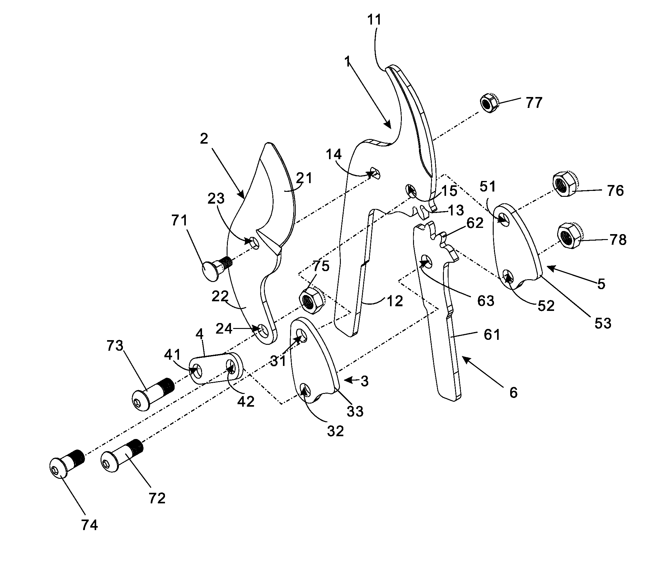
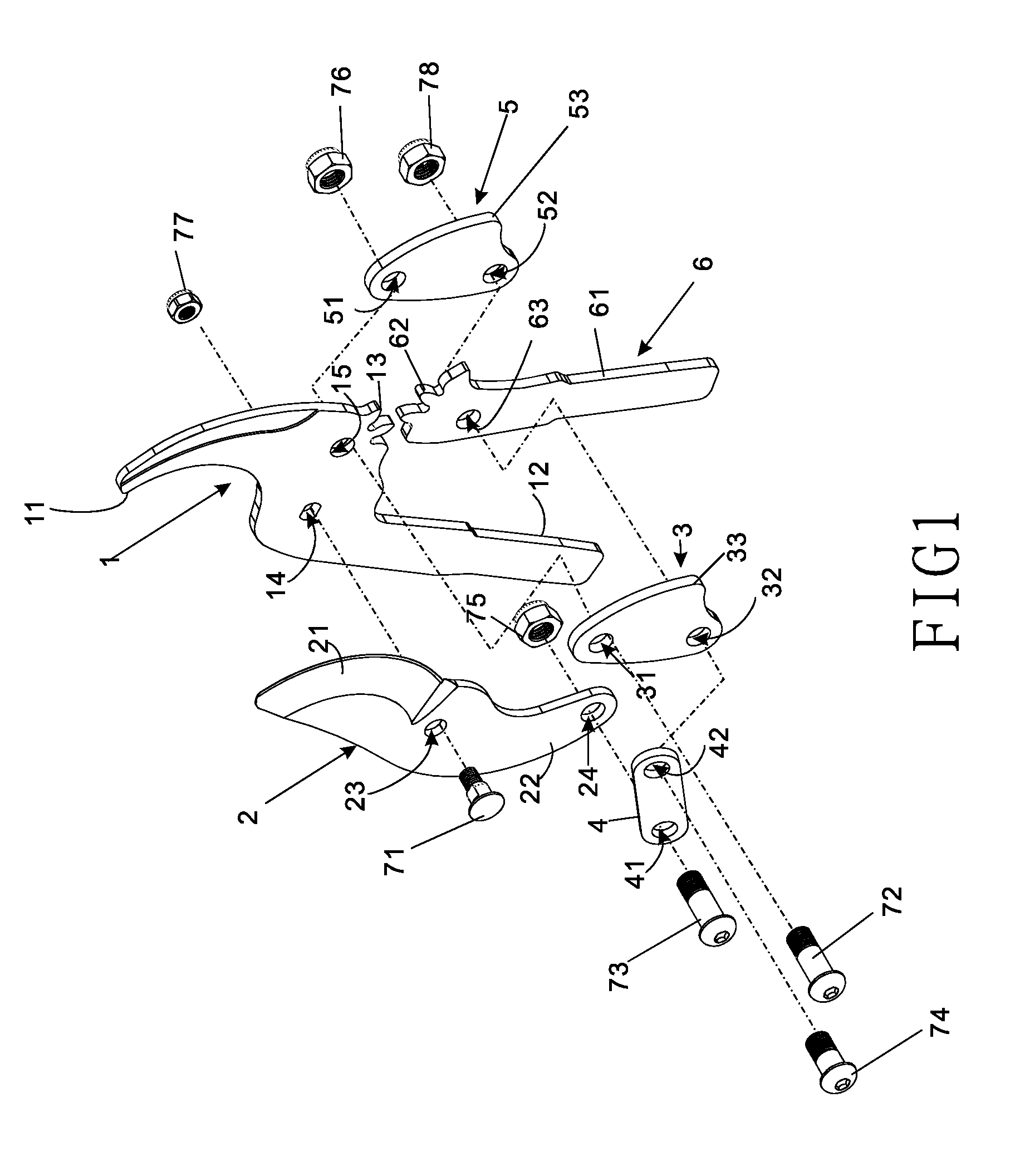
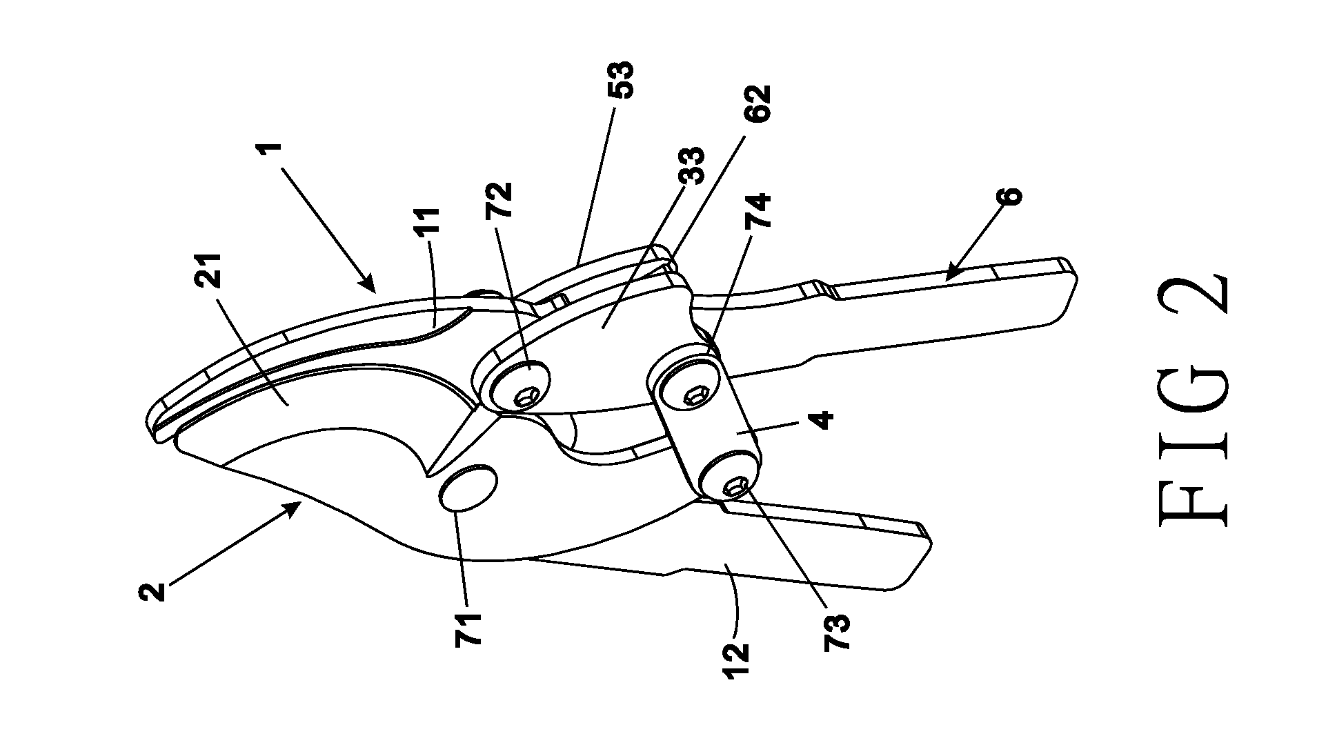
[0015]Refer to FIG. 1, a pruning shears of the present invention includes a first brake arm 1, a second brake arm 6, a blade 2, a connection piece 4, a first cover portion 3, and a second cover portion 5. The first brake arm 1 consists of a first toothed part 13, a first handle part 12 and a blunt part 11. A first axial part 14 and a second axial part 15 are disposed under the blunt part 11 while the first toothed part 13 is arranged between the blunt part 11 and the first handle part 12. The second brake arm 6 is composed of a second handle part 61, a second toothed part 62, and an assembly part 63 located between the second handle part 61 and the second toothed part 62. The first toothed part 13 and the second toothed part 62 are engaged with each other. The blade 2 includes a blade part 21, a third handle part 22, a first assembly part 23 and a second assembly part 24. Both the first assembly part 23 and the second assembly part 24 are disposed on the third handle part 22. The co...


PUM


Abstract

A pruning shears is revealed. The pruning shears include a first brake arm, a second brake arm, a blade, and at least one connection piece. The first brake arm is disposed with a first toothed part while the second brake arm is arranged with a second toothed part. The first toothed part and the second toothed part are engaged with each other. The connection piece is pivotally connected to the blade, the first brake arm, and the second brake arm. During a cutting process (pruning process), a force applied is reduced due to the connection piece pivotally connected to the first brake arm and the second brake arm. While the first and the second toothed parts are engaged with each other, the connection piece becomes a wall of the first and the second toothed parts for stabilizing the engagement of the first and the second toothed parts.

Description

NOTICE OF COPYRIGHT[0001]A portion of the disclosure of this patent document contains material which is subject to copyright protection. The copyright owner has no objection to any reproduction by anyone of the patent disclosure, as it appears in the United States Patent and Trademark Office patent files or records, but otherwise reserves all copyright rights whatsoever.BACKGROUND OF THE PRESENT INVENTION[0002]1. Field of Invention[0003]The present invention relates to pruning shears used in gardening, especially to pruning shears for trimming hard branches of trees, plants and fences. A stronger cutting force is required for pruning these plants so that the present invention provides a cutting structure with features of labor-saving and stability.[0004]2. Description of Related Arts[0005]Refer to EP1827770, a pair of clippers, especially hedge clippers, is revealed. Disclosed are manually operated clippers, especially hedge clippers, comprising a toothed gear (ZG, ZS) that is locat...

Claims


Application Information

Patent Timeline
IPC IPC(8): A01G3/02B26B13/26
CPCB26B13/26A01G3/021
Inventor HSU, WEI-CHUN
Owner FORMOSA TOOLS
Why Eureka
Try Eureka