Wrist structure for an articulated robotic arm

a robotic arm and wrist joint technology, applied in the direction of joints, manipulators, manufacturing tools, etc., can solve the problems of limited number of cables that can be inserted through the central hole, limited torque capability, restricted rotation angle of the wrist joint, etc., to improve installation and maintenance convenience, reduce the number of cables inserted, and increase the size of the wiring hole

Active Publication Date: 2016-04-28
HIWIN TECH
View PDF8 Cites 28 Cited by
  • Summary
  • Abstract
  • Description
  • Claims
  • Application Information

AI Technical Summary

Benefits of technology

[0009]The primary objective of the present invention is to provide a wrist structure for an articulated robotic arm, which is capable reducing the number of cables inserted in the wiring hole of the wrist

Problems solved by technology

Besides, the structural strength of the rotary member 14 is low, which results in a low torque capability and a restricted rotation angle of the wrist joint 13.
However, the number of cables that can insert through the central hole is limited by the size of the central hole of the hollow reduction gear.
Ther

Method used


Image

  • Wrist structure for an articulated robotic arm
  • Wrist structure for an articulated robotic arm
  • Wrist structure for an articulated robotic arm

Examples


Embodiment Construction

[0027]The present invention will be clearer from the following description when viewed together with the accompanying drawings, which show, for purpose of illustrations only, the preferred embodiment in accordance with the present invention.

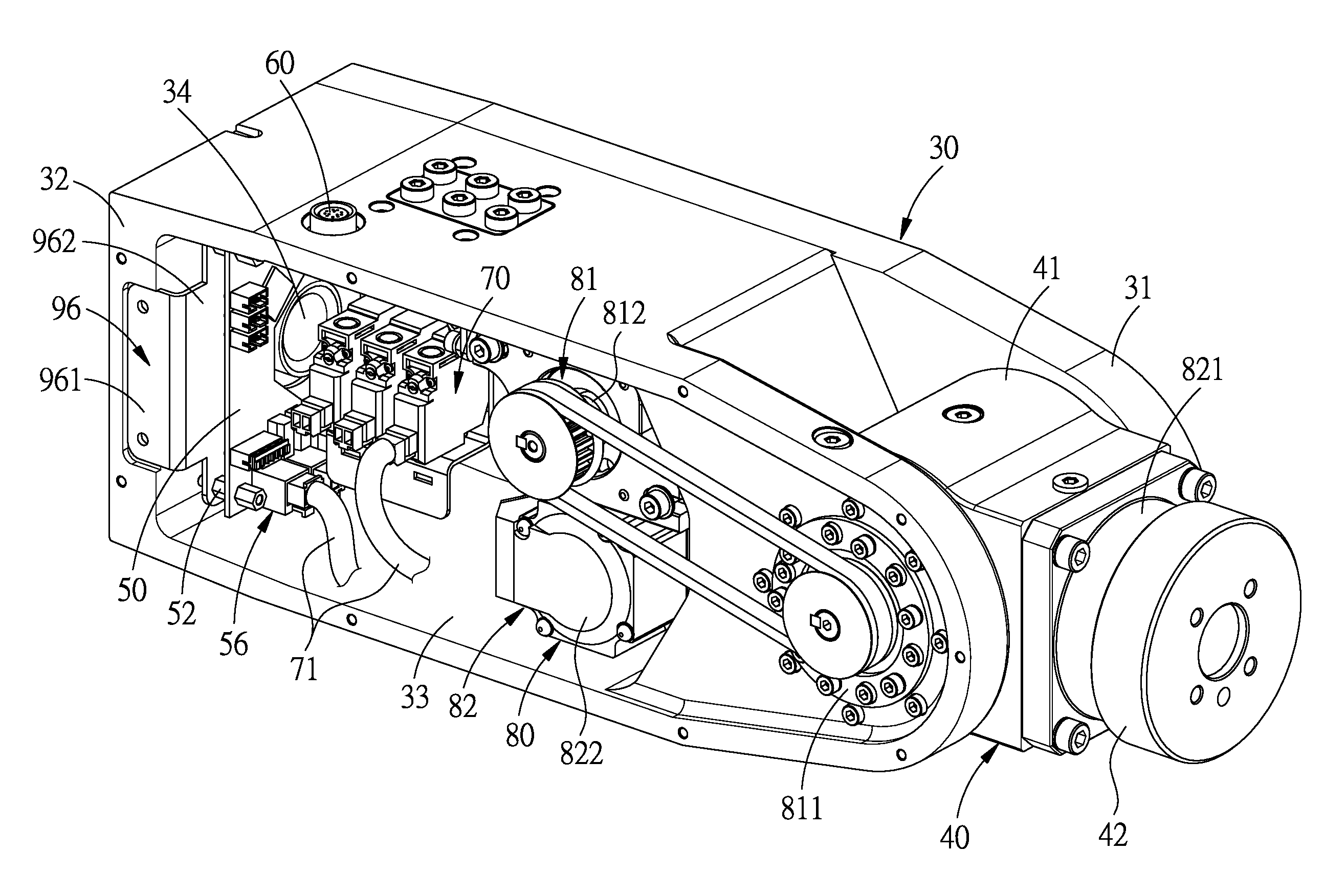
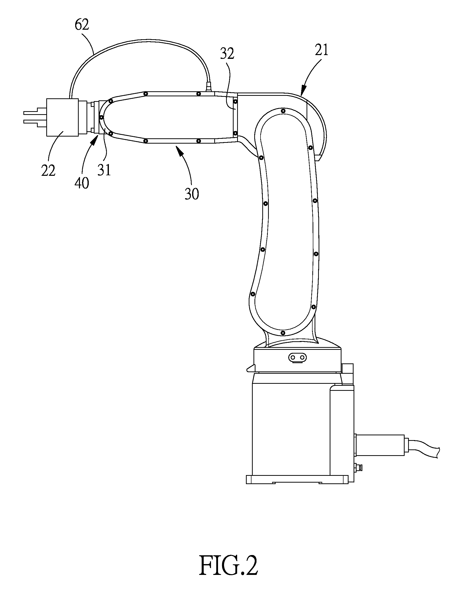
[0028]Referring to FIGS. 2-8, a wrist structure for an articulated robotic arm in accordance with a preferred embodiment of the present invention is suitable for use in an arm body 21 of the articulated robotic arm and provided with an end effector 22. The wrist structure comprises a wrist body 30, a rotary member 40, a signal processing circuit board 50, a connector 60, a control unit 70 and a drive unit 80.

[0029]The wrist body 30 includes a front end portion 31, a rear end portion 32, a receiving portion 33 between the front and rear end portions 31, 32, and a wiring hole 34 formed in the rear end portion 32 to enable the receiving portion 33 to be in communication with the exterior of the wrist body 30. In this embodiment, the rear end portion...


PUM


Abstract

A wrist structure for an articulated robotic arm includes: a wrist body, a rotary member, a signal processing circuit board, a connector, a control unit and a drive unit. The wrist body includes a front end portion, a rear end portion, a receiving portion, and a wiring hole formed in the rear end portion. The rotary member is rotatably connected to the front end portion. The signal processing circuit board is removably disposed at the rear end portion, located inside the receiving portion and includes a gap aligned with the wiring hole. The connector is disposed in the wrist body and signal connected to the signal processing circuit board. The control unit is disposed inside the receiving portion and signal connected to the signal processing circuit board. The drive unit is disposed in the receiving portion to control the rotary member to swing with respect to the wrist body.

Description

BACKGROUND OF THE INVENTION[0001]1. Field of the Invention[0002]The present invention relates to an articulated robotic arm, and more particularly to a wrist structure for an articulated robotic arm.[0003]2. Description of the Prior Art[0004]Robotic arms have found wide application in various equipments due to their versatility and superior operability. For example, the robotic arm used in machining industry can pick up and move objects to a processing machine to enable the objects to be processed by the processing machine in an automatic manner. The robotic arm can also be applied in medical field and controlled by a doctor to perform operation on patients. For a further example, the robotic arm can be used in game play to grab objects.[0005]Referring to FIG. 1, which shows a robotic arm assembly disclosed in U.S. Publication No. 20110154938A1, in order to control the rotation of the motor inside the wrist joint 13, a plurality of cables are inserted from the interior of the arm jo...

Claims


Application Information

Patent Timeline
IPC IPC(8): B25J17/02
CPCB25J17/0258Y10S901/23Y10S901/29B25J19/0029
Inventor LEE, YU-SHANLIU, SHU-HUNG
Owner HIWIN TECH
Why Eureka
Try Eureka