
Electrical contactor and electrical connecting apparatus

Active Publication Date: 2016-04-28
NIHON MICRONICS
View PDF2 Cites 24 Cited by
  • Summary
  • Abstract
  • Description
  • Claims
  • Application Information

AI Technical Summary

Benefits of technology

This patent aims to provide an electrical contactor that can prevent deformation during contact and an electrical connection system that uses this contactor.

Problems solved by technology

As a result, the upper end having the shape of a circular ring of the barrel 2 becomes rough, so that resistance of contact with an external electrode or the like varies among the electrical contactor and does not become stable.
Performance of electrical contact is worsened particularly if the central axis is slightly tilted from the vertical direction or the external electrode is not flat sufficiently.

Method used


Image

  • Electrical contactor and electrical connecting apparatus
  • Electrical contactor and electrical connecting apparatus
  • Electrical contactor and electrical connecting apparatus

Examples


first embodiment

(A) First Embodiment

[0027]A first embodiment of an electrical contactor and that of an electrical connecting apparatus according to this invention are described below by referring to the drawings.

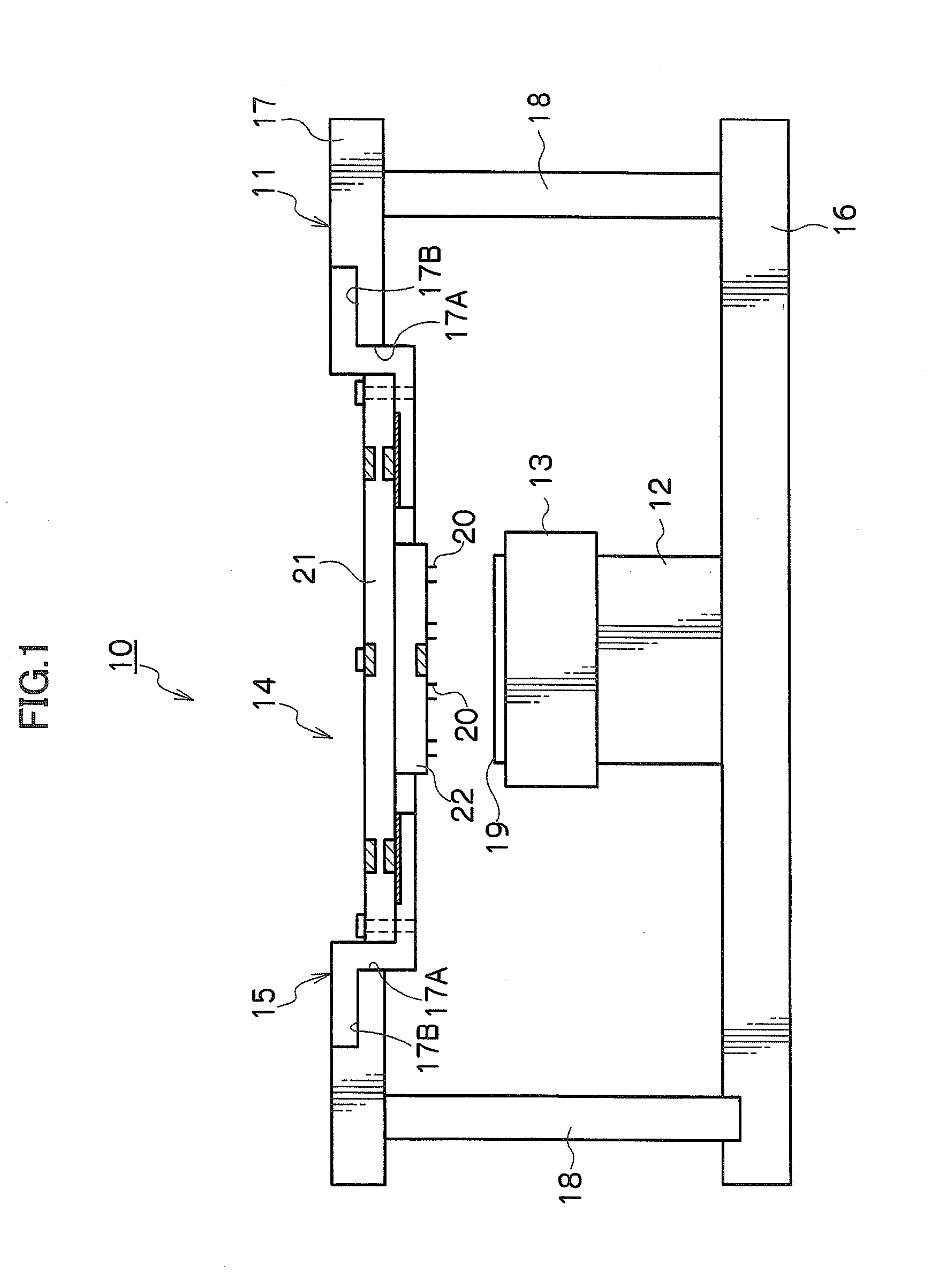
[0028]An inspection device (called a prober in many cases) including the electrical connecting apparatus of the first embodiment employing the electrical contactor of the first embodiment is described first by referring to FIG. 1. The inspection device is not limited to one installed in a way shown in FIG. 1. The “vertical direction” in the following description given by referring to FIG. 1 and subsequent drawings means the vertical direction of FIG. 1.

[0029]An inspection device 10 mainly includes a device body 11, an XYXθ stage 12, a chuck 13, a card connector (called a probe card in many cases) 14, and a connector holder 15.

[0030]The device body 11 is a member to support the XYXθ stage 12, the card connector 14 and the like. The device body 11 mainly includes a lower base 16, an upper bas...


PUM


Abstract

An object of the present invention is to provide an electrical contactor highly resistant to deformation capable of achieving satisfactory performance of electrical contact with a small number of elements.An electrical contactor of this invention includes a barrel having a spring part achieving a spring function formed in a partial section, and a first plunger and a second plunger inserted in the barrel through an opening at one end and an opening at an opposite end of the barrel and fixed to the barrel. It is preferable that an end part of the first plunger in the barrel and an end part of the second plunger in the barrel are placed in internal space of the same non-spring part not to achieve a spring function. It is preferable that the barrel has three or more spring parts separated while non-spring parts are placed between the spring parts.

Description

CROSS-REFERENCE TO RELATED APPLICATION[0001]This application claims, under 35 USC 119, priority of Japanese Application No. 2014-215311 filed on Oct. 22, 2014.BACKGROUND OF THE INVENTION[0002]1. Technical Field Relating to the Invention[0003]This invention relates to an electrical contactor and an electrical connecting apparatus that are for example applicable as an electrical contactor to contact an electrode provided in a wiring substrate, a semiconductor integrated circuit or the like and an electrical connecting apparatus having multiple electrical contactors.[0004]2. Background of Related Art[0005]A well-known electrical contactor is to electrically connect electrical circuits on wiring substrates arranged to face each other, for example. An example of such an electrical contactor can be found in patent document 1 (Japanese Patent Laid-Open No. 2013-7730) (in patent document 1, the electrical contactor is called a probe).[0006]FIG. 10 is a vertical sectional view showing an ele...

Claims


Application Information

Patent Timeline
IPC IPC(8): H01R13/24
CPCH01R13/2421G01R1/06722G01R1/07314G01R1/06733G01R1/06738
Inventor NASU, MIKAAABERGE, DARREN RUSSELLANDO, HIROYASU
Owner NIHON MICRONICS
Features
  • Generate Ideas
  • Intellectual Property
  • Life Sciences
  • Materials
  • Tech Scout
  • Unparalleled Data Quality
  • Higher Quality Content
  • 60% Fewer Hallucinations
Learn More