
Distortion-compensating power amplifier and method for compensating for distortion to amplify power

a power amplifier and distortion compensation technology, applied in the direction of amplifiers with back-off control, amplifiers to reduce non-linear distortion, etc., can solve the problems of increasing interference with adjacent channels, difficult to achieve high power output and high efficiency while, and increasing the leakage power of adjacent channels. , to achieve the effect of reducing interference with communication in adjacent channels

Inactive Publication Date: 2016-04-28
PANASONIC CORP
View PDF1 Cites 8 Cited by
  • Summary
  • Abstract
  • Description
  • Claims
  • Application Information

AI Technical Summary

Benefits of technology

The patent text describes a power amplifier that can reduce interference with communication in adjacent channels even when the sampling rate of a DAC is not high enough. This means that the amplifier can make it more difficult for signals to interfere with each other, even if the DAC is not perfectly synchronized.

Problems solved by technology

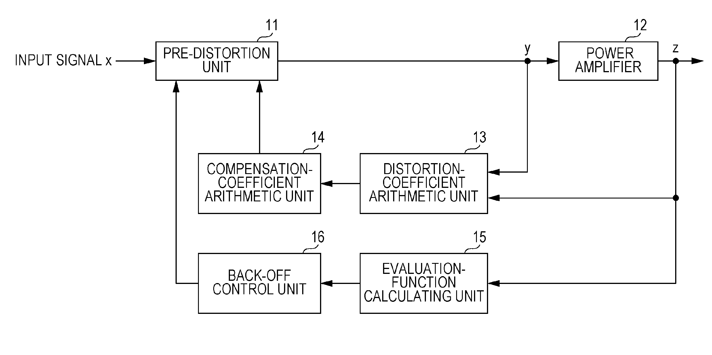
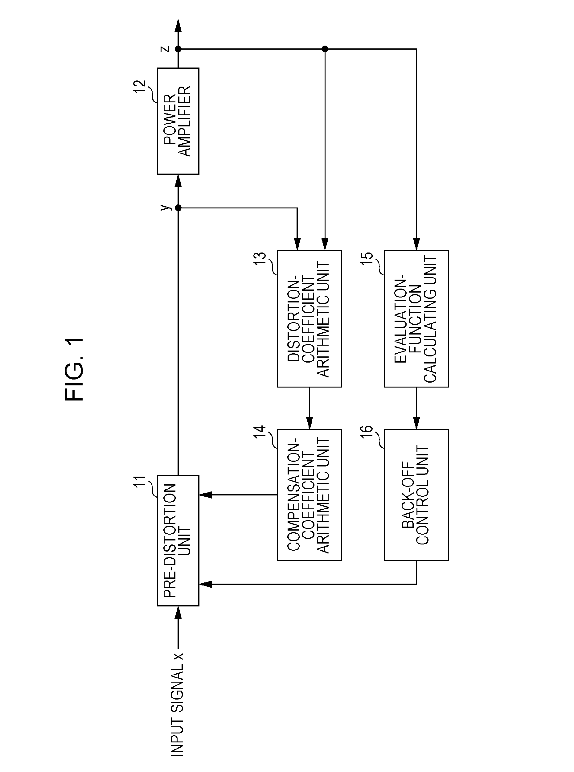
In wireless communication devices provided in mobile equipment, adjacent-channel leakage power increases owing to nonlinear input / output characteristics of power amplifiers.
When the adjacent-channel leakage power increases, interference with the adjacent channels increases.
It is, however, difficult to achieve a high power output and a high efficiency while maintaining high linearity, and it is desired to apply a nonlinear distortion compensation technique.
However, the power amplifiers disclosed in Patent Documents 1 and 2 noted above have a problem as described below.
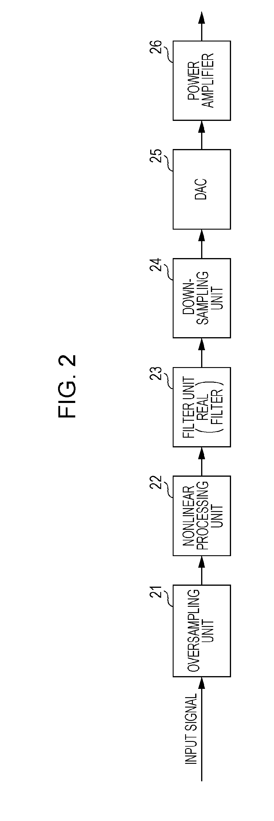
When the sampling rate of a digital-to-analog converter (DAC) is not sufficiently high, it is difficult to suppress adjacent-channel leakage power, causing a problem in that communication in adjacent channels is interfered with.

Method used


Image

  • Distortion-compensating power amplifier and method for compensating for distortion to amplify power
  • Distortion-compensating power amplifier and method for compensating for distortion to amplify power
  • Distortion-compensating power amplifier and method for compensating for distortion to amplify power

Examples


first embodiment

[0054]FIG. 4 is a block diagram illustrating the configuration of a distortion-compensating power amplifier 100 according to a first embodiment of the present disclosure. The following description will be given of the configuration of the distortion-compensating power amplifier 100.

[0055]An up-sampling unit 101 up-samples the sampling rate of an input signal to twice the sampling rate of a DAC 105, suppresses an image signal that is generated during the up-sampling, and outputs the up-sampled signal to a pre-distortion unit 102.

[0056]In accordance with the compensation coefficient, the pre-distortion unit 102 performs pre-distortion processing, which gives distortion having an inverse characteristic of a distortion characteristic that is generated in a power amplifier 107, on the signal output from the up-sampling unit 101 and outputs the resulting signal to a filter unit 103.

[0057]The filter unit 103 is a complex filter having a filter coefficient that is a complex number. The filt...

second embodiment

[0082]FIG. 9 is a block diagram illustrating the configuration of a distortion-compensating power amplifier 300 according to a second embodiment of the present disclosure. FIG. 9 differs from FIG. 4 in that an antenna 301, a power determination unit 302, and an adjacent-channel determination unit 303 are further added and the filter unit 103 is changed to a filter unit 304.

[0083]The power determination unit 302 includes bandpass filters 321-1 and 321-2, power detecting units 322-1 and 322-2, and a comparing unit 323 and determines whether or not reception power of each band of a received signal is larger or smaller.

[0084]The bandpass filters 321-1 and 321-2 are filters for passing specific bands of signals received by the antenna 301. For example, when a communication apparatus having the distortion-compensating power amplifier 300 performs transmission using CH2, one bandpass filter 321-1 passes the band of CH1 (i.e., the channel adjacent to a frequency lower than CH2). The other b...

third embodiment

[0093]Communication between an access point (AP) and a plurality of terminals will be described in a third embodiment of the present disclosure. In FIG. 11, the AP can perform communication in parallel by using a plurality of channels CH1 to CH3. The AP recognizes that the through which channel each terminal performs communication, and the AP has, for example, a table illustrated in FIG. 12A or 12B. In the example illustrated in FIG. 11 and FIG. 12A or 12B, terminals A, B, and C perform communication through CH1, terminals D and E perform communication through CH2, and terminal F performs communication through CH3.

[0094]FIG. 13 is a block diagram illustrating the configuration of a distortion-compensating power amplifier 400 according to the third embodiment of the present disclosure. FIG. 13 differs from FIG. 9 in that a packet demodulation unit 401 and a terminal-ID management unit 402 are added, the power determination unit 302 is eliminated, and the adjacent-channel determinatio...


PUM


Abstract

A distortion-compensating power amplifier compensates for nonlinear distortion in a power amplifier. The distortion-compensating power amplifier includes: a predistorter that performs pre-distortion processing, the pre-distortion processing applying an inverse characteristic of a distortion characteristic that is generated in the power amplifier to an input signal; a filter that performs band limitation on the pre-distorted input signal by using a frequency characteristic that is asymmetric with respect to a center frequency of the input signal, the filter having a filter coefficient that is a complex number; a down-sampler that down-samples the band-limited input signal; and a digital-to-analog converter that converts the down-sampled input signal from a digital signal to an analog signal.

Description

BACKGROUND[0001]1. Technical Field[0002]The present disclosure relates to a distortion-compensating power amplifier and a method for compensating for signal nonlinear distortion resulting from power amplification, by performing pre-distortion.[0003]2. Description of the Related Art[0004]In recent years, mobile equipment including, for example mobile phones and notebook computers equipped with wireless communication functions, is becoming increasingly widely used. In wireless communication devices provided in mobile equipment, adjacent-channel leakage power increases owing to nonlinear input / output characteristics of power amplifiers. The power amplifiers require high linearity for the input / output characteristics.[0005]For example, in order for mobile equipment using a millimeter wave band to receive large amounts of data of moving images or to deliver different large amounts of data to respective users in parallel, adjacent channels are assigned to the users. When the adjacent-chan...

Claims


Application Information

Patent Timeline
Patent Type & Authority Applications(United States)
IPC IPC(8): H03F1/32H03F3/21H03F1/02
CPCH03F1/3247H03F1/0205H03F2201/3227H03F2201/3215H03F3/21H03F3/245H03F2201/3203
Inventor MIYANAGA, KENJITAKINAMI, KOJI
Owner PANASONIC CORP
Learn More