Eureka AIR delivers breakthrough ideas for toughest innovation challenges, trusted by R&D personnel around the world.

Dual Horsehead Block And Tackle Pumping Unit

a pumping unit and double-horsehead technology, applied in the direction of piston pumps, gearing, borehole/well accessories, etc., can solve the problems of low mechanical efficiency, high manufacturing cost, poor balancing, etc., and achieve the effect of low cost, low energy consumption, and maximum stroke length

Inactive Publication Date: 2016-05-05
WANG YI +2
View PDF0 Cites 6 Cited by
  • Summary
  • Abstract
  • Description
  • Claims
  • Application Information

AI Technical Summary

Benefits of technology

The invention is a pumping unit that uses a dual horsehead block and tackle beam to achieve a maximum stroke length and low cost. It is a simple structure and easy to use. The unit eliminates parts typically found in conventional units, such as a crank, counterweight, and multiple reducers, reducing weight and cost. It has low manufacture and energy consumption, high reliability and safety, and can be used for both single and dual well operations. The unique design also reduces the load on the pulling wire rope, increasing service life. Overall, the pumping unit offers improved efficiency and reliability in oil production.

Problems solved by technology

However, there are several disadvantages including large peak torque, low mechanical efficiency, poor balancing, high manufacturing costs, and high energy consumption, which prevent further improvement of the oil production efficiency and cost efficiency.
This wiring method of the pulling wire rope has the following defects: 1. The pulling wire rope passes through an additional guide wheel which increases the number of times the pulling wire rope is bent, which in turn affects the service life of the pulling wire rope.
Therefore, a sucker rod does not have enough stroke length.
Experiments have proved that this design is not practical.

Method used


Image

  • Dual Horsehead Block And Tackle Pumping Unit
  • Dual Horsehead Block And Tackle Pumping Unit
  • Dual Horsehead Block And Tackle Pumping Unit

Examples


Embodiment Construction

[0022]A further demonstration of the dual horsehead block and tackle beam pumping unit 100 combined with drawings and implementations of specific embodiments is disclosed herein.

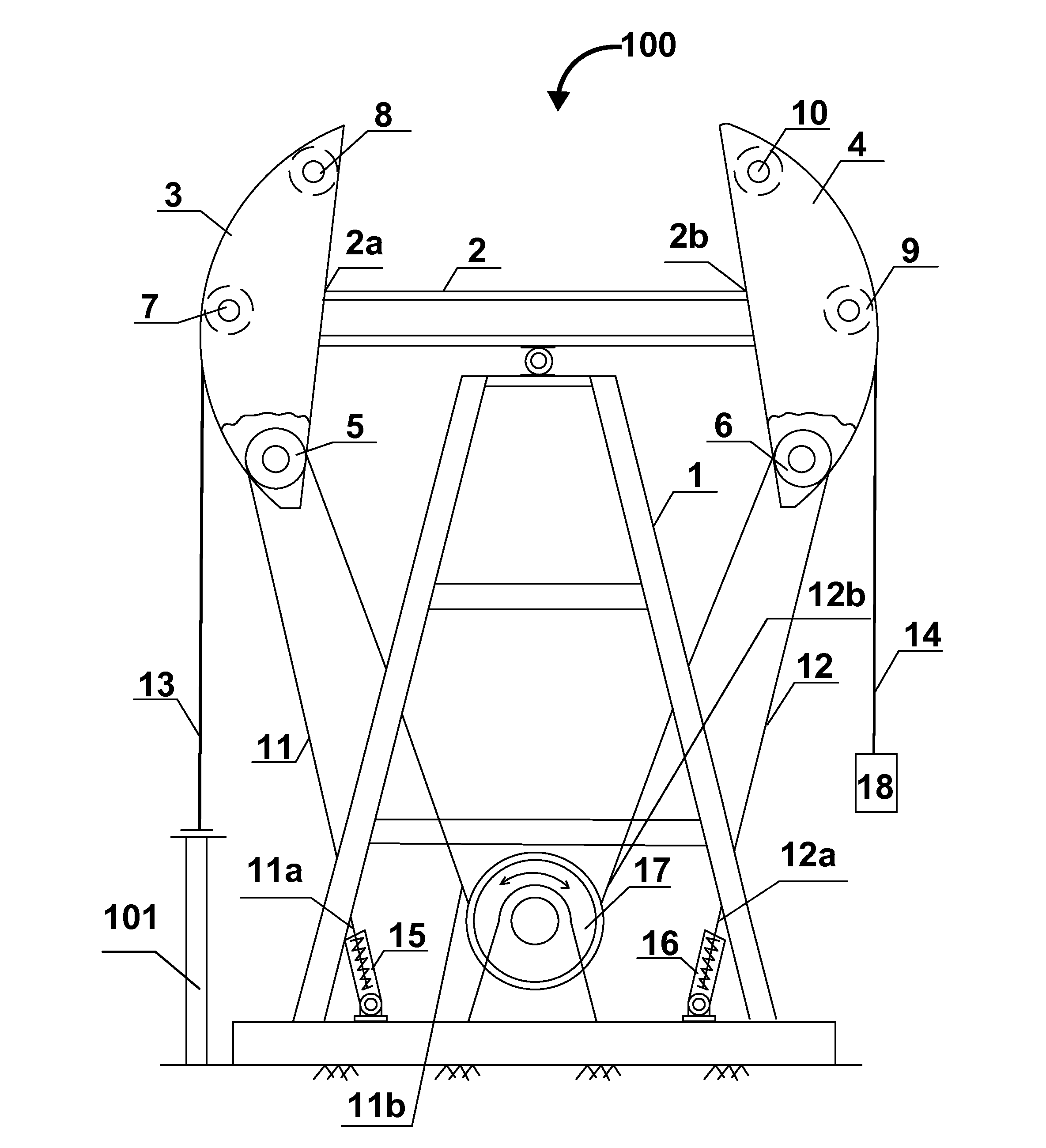
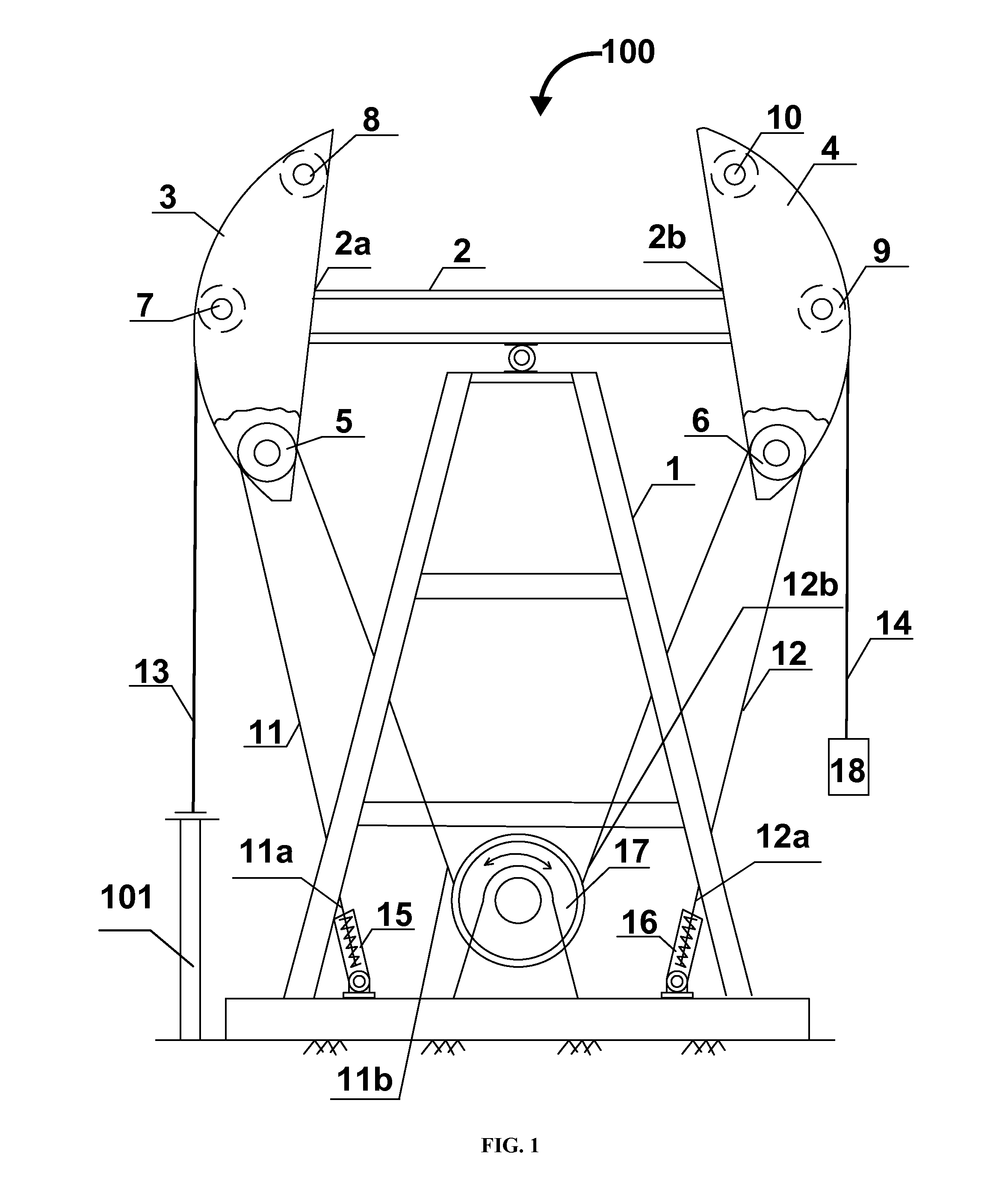
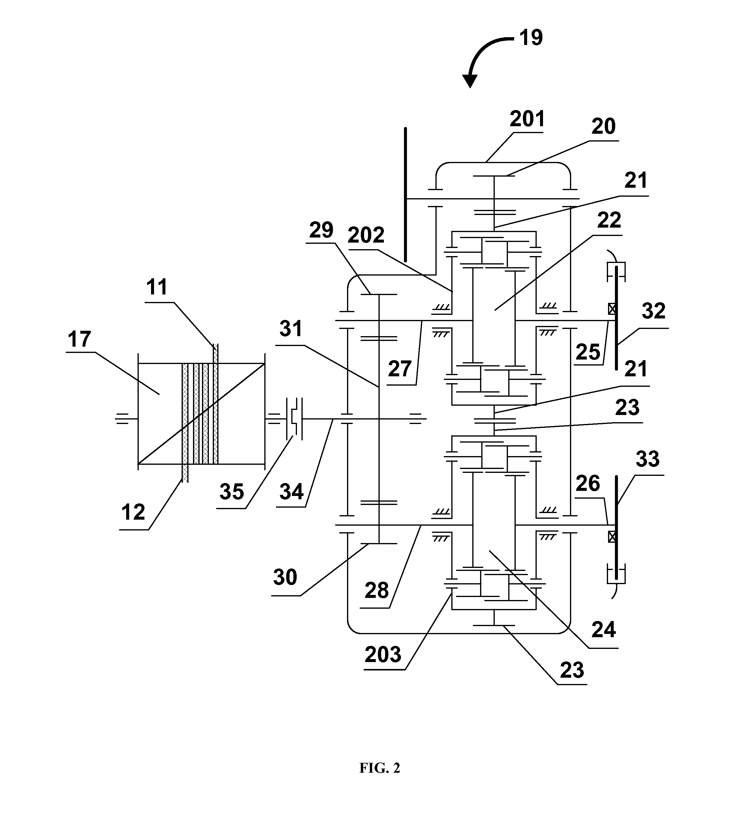
[0023]As illustrated by FIG. 1, the dual horsehead block and tackle beam pumping unit 100 comprises a steel frame 1, a walking beam 2, horseheads 3 and 4, movable pulleys 5 and 6, pulling wire ropes 11 and 12, load wire ropes 13 and 14, damping extension springs 15 and 16, an output drum 17, a counterweight box 18, a reversing reducer 19 illustrated in FIG. 2, reversing brake mechanisms 32 and 33 illustrated in FIG. 2, and an electric motor. The reversing reducer 19 and the electric motor are not shown in FIG. 1. The structure of the dual horsehead block and tackle beam pumping unit 100 is as aforementioned and is a balanced structure in general. The walking beam 2 is installed on top of the steel frame 1. The horseheads 3 and 4 are installed on opposing ends 2a and 2b of the walking beam 2 respectively, and...


PUM


Abstract

A dual horsehead block and tackle beam pumping unit including a steel frame, a walking beam installed on top of the steel frame, horseheads with movable pulleys, pulling wire ropes, load wire ropes, damping extension springs, a reversing reducer, an output drum, a counterweight box, reversing brake mechanisms, and an electric motor is provided for single well and dual well operations. The horseheads are installed on opposing ends of the walking beam. The movable pulley of each horsehead has a pulling wire rope. The first and second ends of each pulling wire rope are connected to the damping extension spring and the output drum respectively. A lower end of the load wire rope hanging on the right hand side horsehead is connected to the counterweight box. On the bottom of the steel frame, the electric motor, the reversing reducer, and the output drum are installed on a base.

Description

CROSS-REFERENCE TO RELATED APPLICATIONS[0001]This application claims priority to and the benefit of the non-provisional patent application number 201410647479.8 titled “Dual Horsehead Block and Tackle Pumping Unit”, filed in the State Intellectual Property Office of the People's Republic of China on Nov. 3, 2014. The specification of the above referenced patent application is incorporated herein by reference in its entirety.FIELD OF THE INVENTION[0002]This invention discloses an oil production apparatus used in oil fields, and more specifically, a dual horsehead block and tackle beam pumping unit.BACKGROUND[0003]Conventional beam pumping units have long been the mainstream mechanical equipment for worldwide oil production. The conventional beam pumping units adopt a four-bar linkage mechanism and have advantages such as a reasonable velocity curve and decent reliability. However, there are several disadvantages including large peak torque, low mechanical efficiency, poor balancing, ...

Claims


Application Information

Patent Timeline
IPC IPC(8): E21B43/12F04B49/02F04B17/03F04B47/02
CPCE21B43/121F04B47/022E21B2043/125F04B49/022F04B17/03F04B47/028E21B43/00E21B43/127F16H3/666
Inventor WANG, YIWANG, JINYANG, ZIJIANG
Owner WANG YI
Why Eureka
Eureka Blog
Learn More