
Mobile equipment and sliding structure therefor

a mobile equipment and sliding technology, applied in the direction of substation equipment, telephone set construction, electrical apparatus, etc., can solve the problems of substantial inability to operate, the housing structure of sliding mobile equipment disclosed in those conventional examples, and the inability to reserve great strokes, etc., to achieve simple mechanism, small size, and high strength

Inactive Publication Date: 2014-10-07
NEC CORP
View PDF38 Cites 1 Cited by
  • Summary
  • Abstract
  • Description
  • Claims
  • Application Information

AI Technical Summary

Benefits of technology

The present invention provides a sliding mechanism for a mobile device that is simple, small in size, and strong, but can still take a large stroking distance and protect the display from damage. It is designed to maintain a thin and flexible structure while still being highly rigid. This invention allows for the creation of a mobile device with a sliding mechanism that is both effective and easy to use.

Problems solved by technology

In the folded type, although an erroneous operation can be prevented when the mobile equipment is carried, the operation is substantially impossible in the folded state, since the display cannot be viewed.
The housing structures of the sliding type mobile equipments disclosed in those conventional examples have several problems.
At first, a great stroke cannot be reserved unlike that of the folded type mobile equipment.
However, when the distance is made excessively short, a gap for the sliding appears as an angle when it is inclined.
As a result, the stroke is limited.
However, even if the display can be always checked as the sliding type mobile phone, this is not meaningful if the apparatus becomes large.
In this case, the display is likely to be broken because the displaying parts such as a liquid crystal panel are usually made of glass.

Method used


Image

  • Mobile equipment and sliding structure therefor
  • Mobile equipment and sliding structure therefor
  • Mobile equipment and sliding structure therefor

Examples


Embodiment Construction

[0031]Thereinafter, the mobile equipment and the sliding mechanism thereof according to the exemplary embodiments of the present invention will be described with reference to the attached drawings. Here, as the mobile equipment, a mobile phone will be described as an example. However, the present invention is not limited to this example. The present invention can be applied to even a different mobile equipment such as a digital camera, an electronic notebook and a mobile game machine.

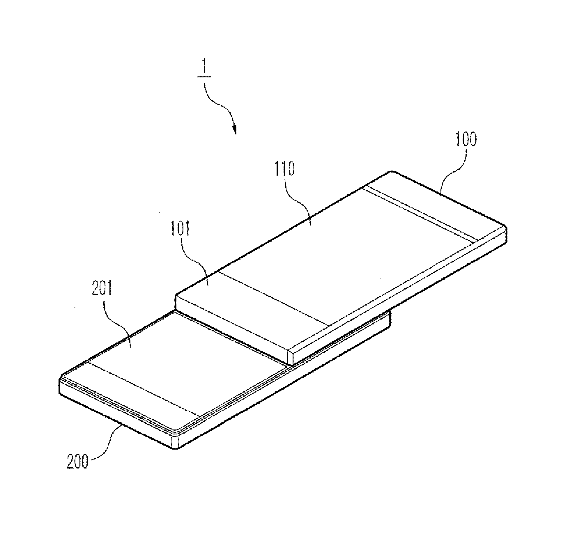
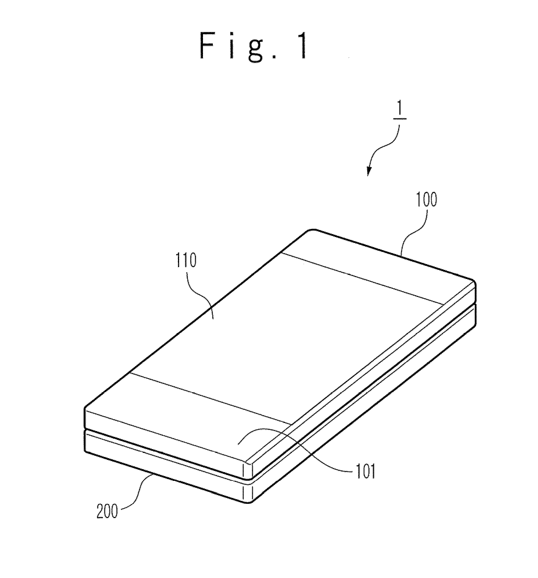
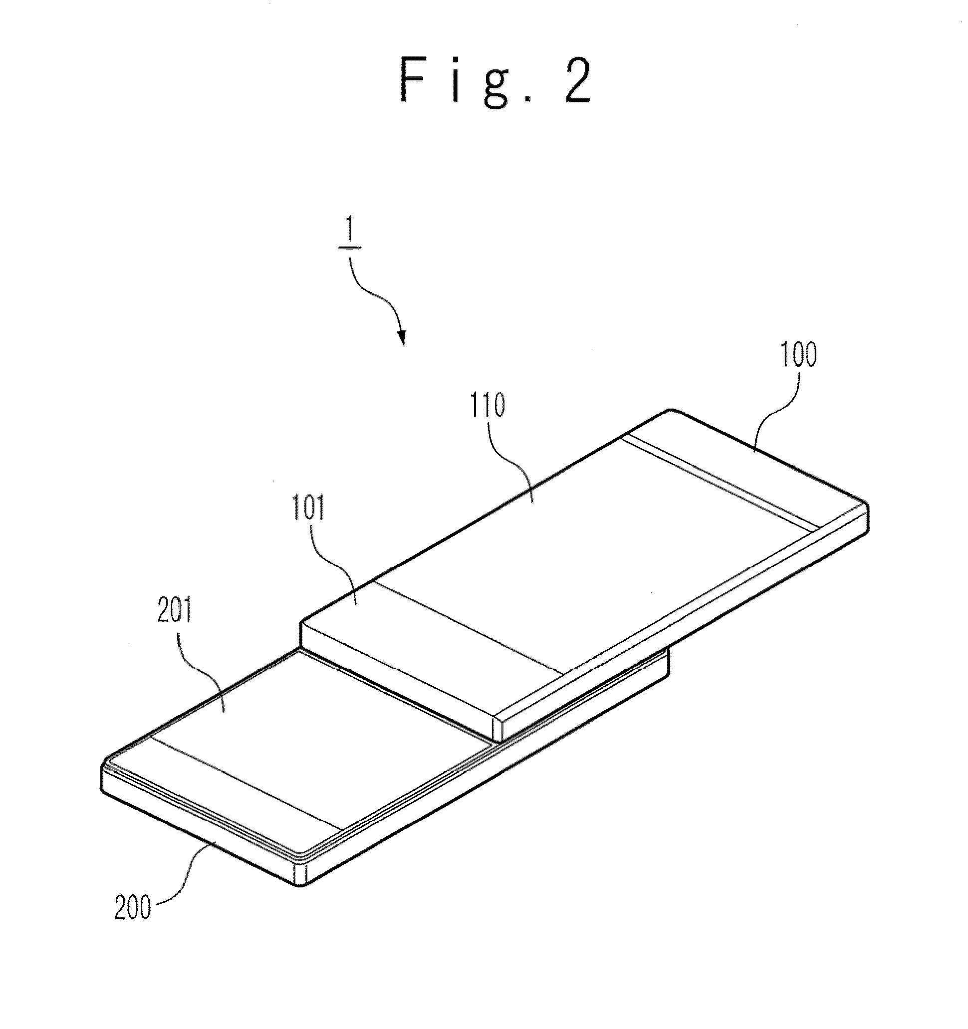
[0032]FIGS. 1 and 2 are perspective views showing the configuration of the mobile phone to which the sliding mechanism of the mobile equipment according to an exemplary embodiment of the present invention is applied. FIG. 1 shows an accommodation state, and FIG. 2 shows an extension state.

[0033]A mobile phone 1 is mainly divided into an upper housing 100 and a lower housing 200. A receiver, a display, basic operation keys, and a sub board (these parts are not shown) are built in the upper housing 100. T...


PUM


Abstract

A sliding structure is for a mobile equipment which includes a second housing and a first housing slidably provided for the second housing. The sliding structure includes a display frame configured to accommodate a display unit of the first housing and having slide grooves provided for side walls parallel to a direction of the slide, and a slide support section provided along side walls of said second housing in parallel to the slide direction such that tip portions of said slide support section slidably engage with said slide grooves. Although having a simple mechanism, the mobile equipment has a small size and high strength, and can take a large stroke length. In this way, the sliding mechanism for the mobile equipment which has high stiffness and the mobile equipment can be provided in which a damage of the display unit can be prevented while maintaining the small size and a thin structure.

Description

TECHNICAL FIELD[0001]The present invention relates to a sliding structure of a mobile equipment and a mobile equipment using it, and more particularly relates to a structure of a sliding mechanism of a mobile equipment such as a mobile phone, a digital camera, and an electronic notebook, and a mobile equipment using its structure.BACKGROUND ART[0002]In recent years, in a mobile equipment, portability is improved and usage applications spread to various fields such as transmission / reception of electronic mail, use of the Internet and a game function as well as simple speech call. For this reason, a mobile equipment is developed to have various mechanisms for a large screen of display unit and operability in character input. For example, a folded type of mobile equipment is carried in a folded state usually and is developed at the time of speech communication or mail transmission, to facilitate to view a large screen display and to input characters and commends, thereby allowing vario...

Claims


Application Information

Patent Timeline
Patent Type & Authority Patents(United States)
IPC IPC(8): H04M1/00H04M1/02
CPCH04M1/0237
Inventor OGATSU, TOSHINOBU
Owner NEC CORP
Learn More