Method and a circuit for ventilating equipment of a turbojet by thermoelectricity

a technology of thermoelectricity and equipment, which is applied in the direction of positive displacement liquid engines, piston pumps, liquid fuel engines, etc., can solve the problems of increasing the drag of such turbojets, ineffective solutions, and no longer conveying cold air to equipment for the purpose of ventilating, so as to limit the overuse of the ventilation circuit

Inactive Publication Date: 2016-05-05
SN DETUDE & DE CONSTR DE MOTEURS DAVIATION S N E C M A
View PDF11 Cites 32 Cited by
  • Summary
  • Abstract
  • Description
  • Claims
  • Application Information

AI Technical Summary

Benefits of technology

[0017]This characteristic seeks to stop ventilation of the equipment before temperature equilibrium is established between the ventilation space and the secondary air stream passage. This makes it possible to limit overuse of the ventilation circuit when there is no need to bring the temperature of the equipment to such a low temperature.

Problems solved by technology

Unfortunately, for high bypass ratio turbojets, arranging equipment around the fan would lead to increasing the drag of such turbojets.
Nevertheless, once the engine has stopped, cold air is no longer conveyed to the equipment for the purpose of ventilating it, even though the high-pressure body of the turbojet is still very hot and continues to radiate so that the temperature of the equipment rises before cooling very progressively.
Nevertheless, that solution is made ineffective by numerous additional pieces of equipment being incorporated in the space around the high-pressure body of the turbojet, which pieces of equipment are usually not designed to withstand such temperatures.
Furthermore, for reasons of independence between systems, airplane manufacturers are generally reticent about supplying auxiliary energy to the engine when it is stopped.
In addition, powering fans from the batteries of the airplane requires the batteries to be dimensioned accordingly, and that necessarily makes them heavier.

Method used


Image

  • Method and a circuit for ventilating equipment of a turbojet by thermoelectricity
  • Method and a circuit for ventilating equipment of a turbojet by thermoelectricity

Examples


Embodiment Construction

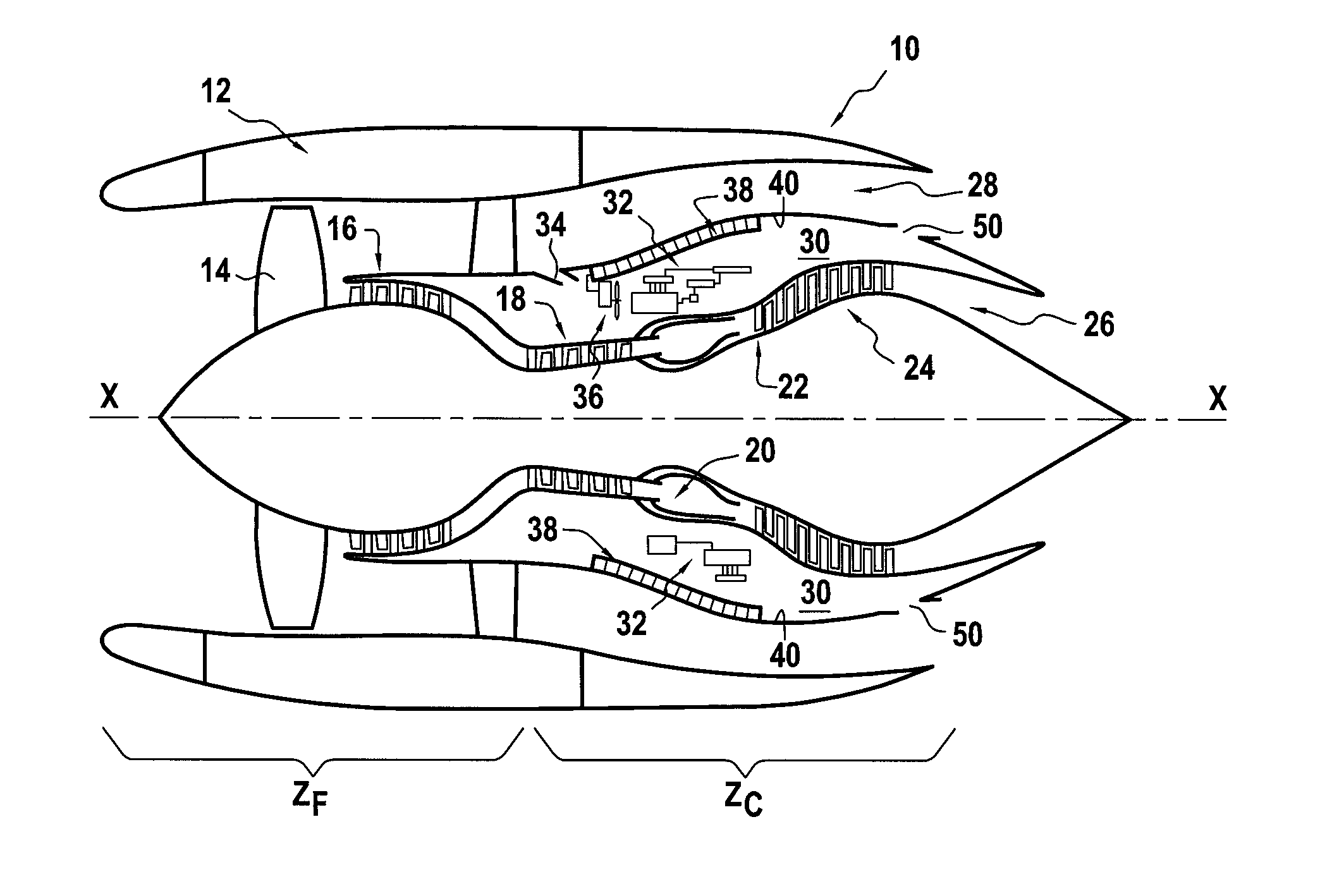
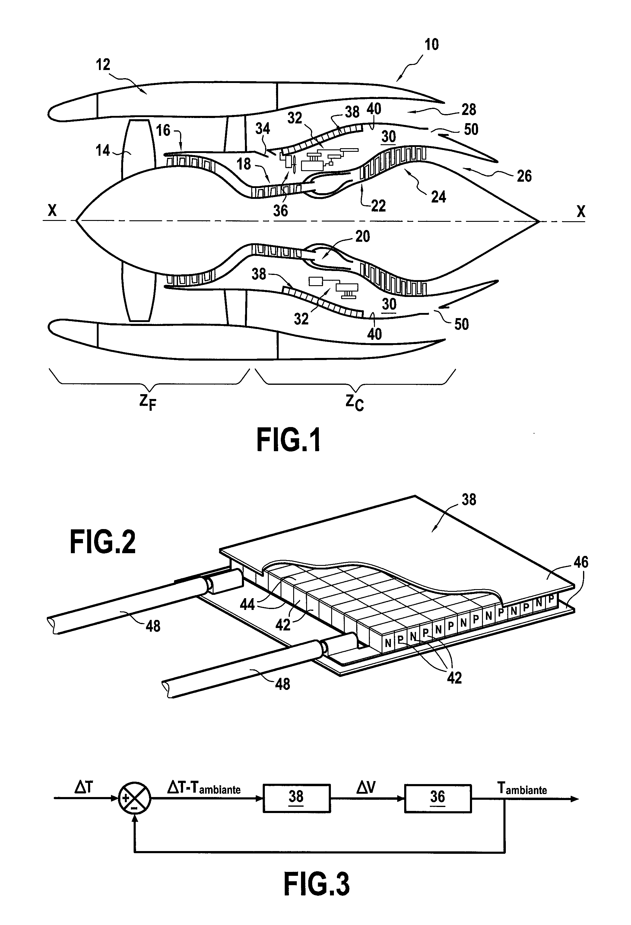
[0026]FIG. 1 is a diagrammatic longitudinal section view of an aircraft turbojet 10 of the bypass and double spool type, which turbojet is surrounded by a nacelle 12. In known manner, the turbojet 10 comprises from upstream to downstream: a fan 14, a low-pressure compressor 16, a high-pressure compressor 18, a combustion chamber 20, a high-pressure turbine 22, and a low-pressure turbine 24, which are all centered on a longitudinal axis X-X.

[0027]The turbojet 10 also has a primary air stream passage 26 (for a hot stream) and a secondary air stream passage 28 (for a cold stream) that is formed around the primary stream passage.

[0028]The turbojet 10 also has a cold zone ZF (including in particular the fan 14 and the low-pressure compressor 16) upstream from a hot zone ZC (corresponding to the high-pressure body and including in particular the high-pressure compressor 18 and the combustion chamber 20).

[0029]A ventilation space 30 is defined within the hot zone ZC for receiving various p...


PUM


Abstract

The invention provides a method of ventilating equipment of a turbojet, the turbojet (10) having a cold zone (ZF) including a fan (14) upstream from a hot zone (ZC), the turbojet equipment (32) for ventilating being arranged in a ventilation space (30) available around the hot zone between a primary air stream passage (26) and a secondary air stream passage (28) of the turbojet, the method comprising taking ventilation air from one of the air stream passages in order to convey it to the ventilation space, and providing forced flow of the ventilation air by means of at least one electric fan (36) positioned inside the ventilation space and powered electrically by at least one thermoelectric generator (38) suitable for inducing a potential difference (ΔV) and positioned in a wall (40) between the ventilation space and the secondary air stream passage.

Description

BACKGROUND OF THE INVENTION[0001]The present invention relates to the general field of ventilation of equipment located in the vicinity of the hot zone of a turbojet.[0002]A turbojet has a large amount of auxiliary equipment. This comprises in particular the various accessories of the accessory gearbox (AGB) such as pumps for producing hydraulic energy, fuel supply, lubrication, electricity generators for producing electrical power, etc., together with the hydromechanical unit (HMU) that serves to control the servovalves used for metering the flow rate at which fuel is sent to the hydraulic actuators for actuating the variable geometry components of the turbojet and to the air valves of the engine air circuit.[0003]Such equipment is sensitive to high temperatures and should therefore preferably be arranged in the vicinity of the cold zone of the turbojet, i.e. around its fan, in order to avoid any suffering of the reliability of the equipment from being subjected to high levels of t...

Claims


Application Information

Patent Timeline
Patent Type & Authority Applications(United States)
IPC IPC(8): F01D25/12F04D25/08F01D15/08F04D29/58F01D5/02F04D25/06F04D29/32
CPCF01D25/12F04D25/0673F04D25/082F04D29/325F05D2270/52F01D5/02F01D15/08F05D2220/323F05D2260/221F04D29/5806F05D2220/60F02K1/82
Inventor LE PACHE, GWENOLE YANNDOMECQ, LISE JEANINE LEONIE
Owner SN DETUDE & DE CONSTR DE MOTEURS DAVIATION S N E C M A
Why Eureka
Try Eureka