

Battery System for Mobile Workstation
a mobile workstation and battery technology, applied in the direction of batteries, cell components, vent arrangements, etc., can solve the problem of discarded old batteries to be replaced by powered ones at significant cos
- Summary
- Abstract
- Description
- Claims
- Application Information
AI Technical Summary
Benefits of technology
Problems solved by technology
Method used
Image

Examples
first embodiment
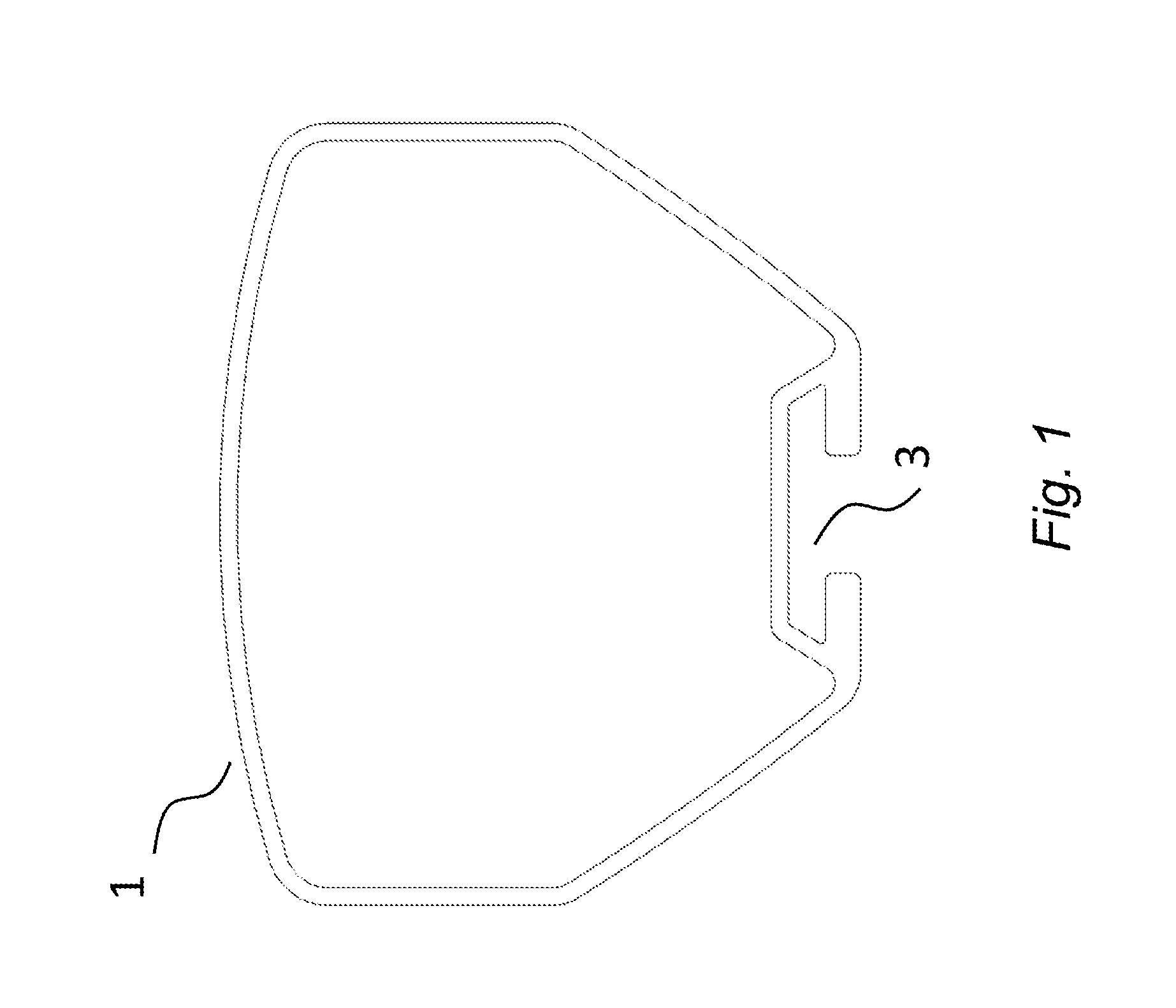
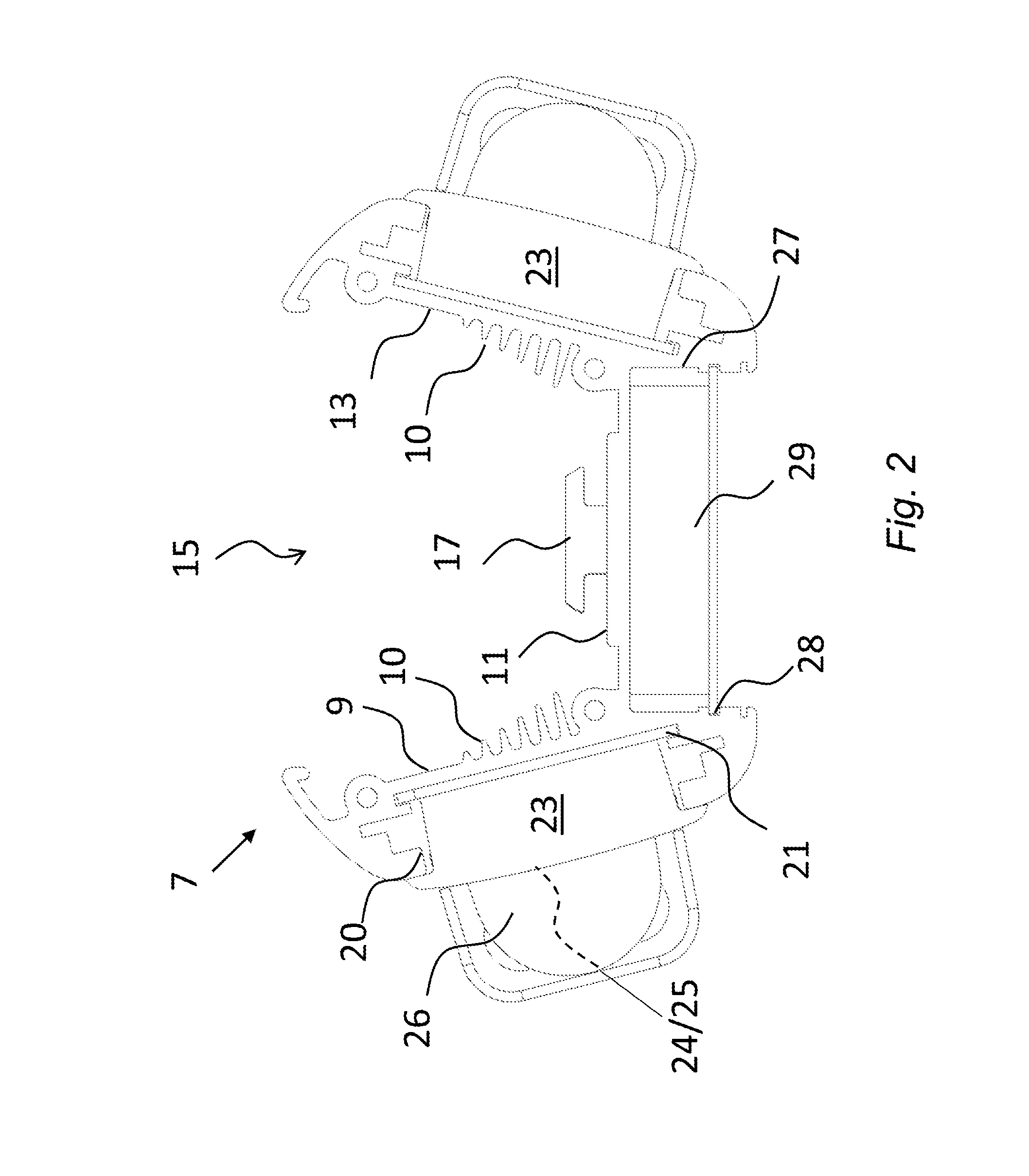
[0053]FIG. 2 shows a first embodiment power system 7 configured to detachably retrofit to the pole 1 shown in FIG. 1.
[0054]The power system 7 comprises a three-sided body defining an inner channel 15 dimensioned to locate snugly around a major part of the extrusion, as indicated in FIG. 3 which shows the two parts inter-connected. The three sides comprise outer walls 9, 13 and an intermediate wall 11. A generally T-shaped tab or tongue 17 is provided, extending into the channel 15 from the centre of the intermediate wall 11 and is shaped and positioned so as to snugly fit inside the vertical channel 3 by means of a tongue-and-groove fit, which can be a friction fit.
[0055]The inner surface of each outer wall 9, 13 carries a series of integrally-formed vertical blades, generally indicated 10, which serve as heat sink elements. The cross-sectional profile of the heat sink elements 10 is arranged such that the footprint conforms substantially to that of the pole exterior around which it...
second embodiment
[0064]A second embodiment power system 37 will now be described with reference to FIGS. 4 to 8.
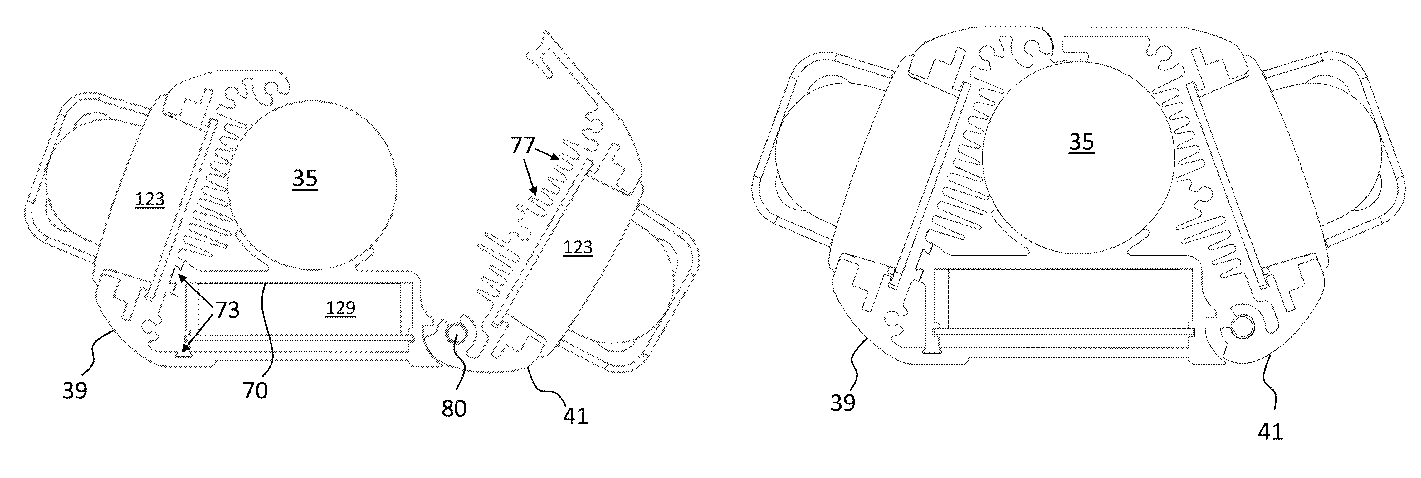
[0065]Referring to FIGS. 4a to 4c, the power system 37 comprises a main body that in use is configured to completely surround a pole 35 in such a way as to clamp onto it, as shown particularly in FIGS. 4c and 4d.
[0066]The body is formed of first and second sections 39, 41 which are hingedly attached by an interconnecting internal rod (not shown) so as to rotate about a vertical axis X-X between open and closed positions. When in the closed position, the sections 39, 41 can be fixed together, for example with a screw system and / or clips. In use, the sections 39, 41 are opened, as shown in FIGS. 4a and 4b, placed around the pole 35, and then closed at which time the dimensions of an interior channel provide a friction fit to the pole, e.g. using an O-ring at the upper and lower ends.
[0067]This power system 37 is configured to carry modular docking units 123 and a modular control unit 129 in...
third embodiment
[0080]A third embodiment power system 100 will now be described with reference to FIGS. 9 to 12. Referring to FIGS. 9 and 10, the power system 100 comprises separate first and second body sections 101, 102 each identical, or near identical, other than their opposed orientations with respect to a circular interior channel 103. The interior channel 103 is formed by U-shaped interior recesses on each body section 101, 102. The body sections 101, 102 when attached together are configured to completely surround a pole to clamp onto it, providing a retro-fit solution.
[0081]Each body section 101, 102 has a main face 105 (covered in FIG. 9) on which is mounted a modular docking unit 109 onto which a rechargeable battery 111 can be removably mounted; each docking unit 109 has the appearance and functionality of the docking units previously described. Two rechargeable batteries 111 can therefore be supported as before, with control circuitry provided as before to manage supply and switching a...
PUM
| Property | Measurement | Unit |
|---|---|---|
| perimeter | aaaaa | aaaaa |
| electrical energy | aaaaa | aaaaa |
| energy | aaaaa | aaaaa |
Abstract
Description
Claims
Application Information