Motor drive controller and control method of motor drive controller

a technology of motor drive controller and control method, which is applied in the direction of electronic commutation motor control, motor/generator/converter stopper, and control of dynamo-electric converters. it can solve the problems of narrow target rotation speed, small number of signal patterns which can be used to set the target speed, and inability to easily configure the command signal input to the motor speed controller. it can easily change the setting of the target rotation speed, and achieve the effect of simple input o

Active Publication Date: 2016-05-05
MINEBEAMITSUMI INC
View PDF3 Cites 5 Cited by
  • Summary
  • Abstract
  • Description
  • Claims
  • Application Information

AI Technical Summary

Benefits of technology

[0008]The present invention is made to solve the above-mentioned problems and one of objects of the present invention is to provide a motor drive controller that can simplify an externally input command signal, easily change the setting of a target rotation speed using a command signal, and has a high degree of freedom in setting the target rotation speed and a control method of the motor drive controller.
[0012]According to the configurations of the illustrative embodiments, a target rotation speed signal is generated based on the determined command step determined based on the input step command signal and the predetermined setting information and a drive control signal is generated based on the generated target rotation speed signal. Therefore, it is possible to provide a motor drive controller that can simplify an input of a command signal from the outside, easily change setting of a target rotation speed using a command signal, and have a high degree of freedom in setting the target rotation speed and a control method of the motor drive controller.

Problems solved by technology

However, the configuration for inputting the command signal to the motor speed controller may not be easily configured.
However, in using such a signal, the number of signal patterns which can be used to set the target speed, and the like, is relatively small.
Accordingly, there may be a problem in that a range in which the target rotation speed can be changed is narrow (the degree of freedom is low).

Method used


Image

  • Motor drive controller and control method of motor drive controller
  • Motor drive controller and control method of motor drive controller
  • Motor drive controller and control method of motor drive controller

Examples


first embodiment

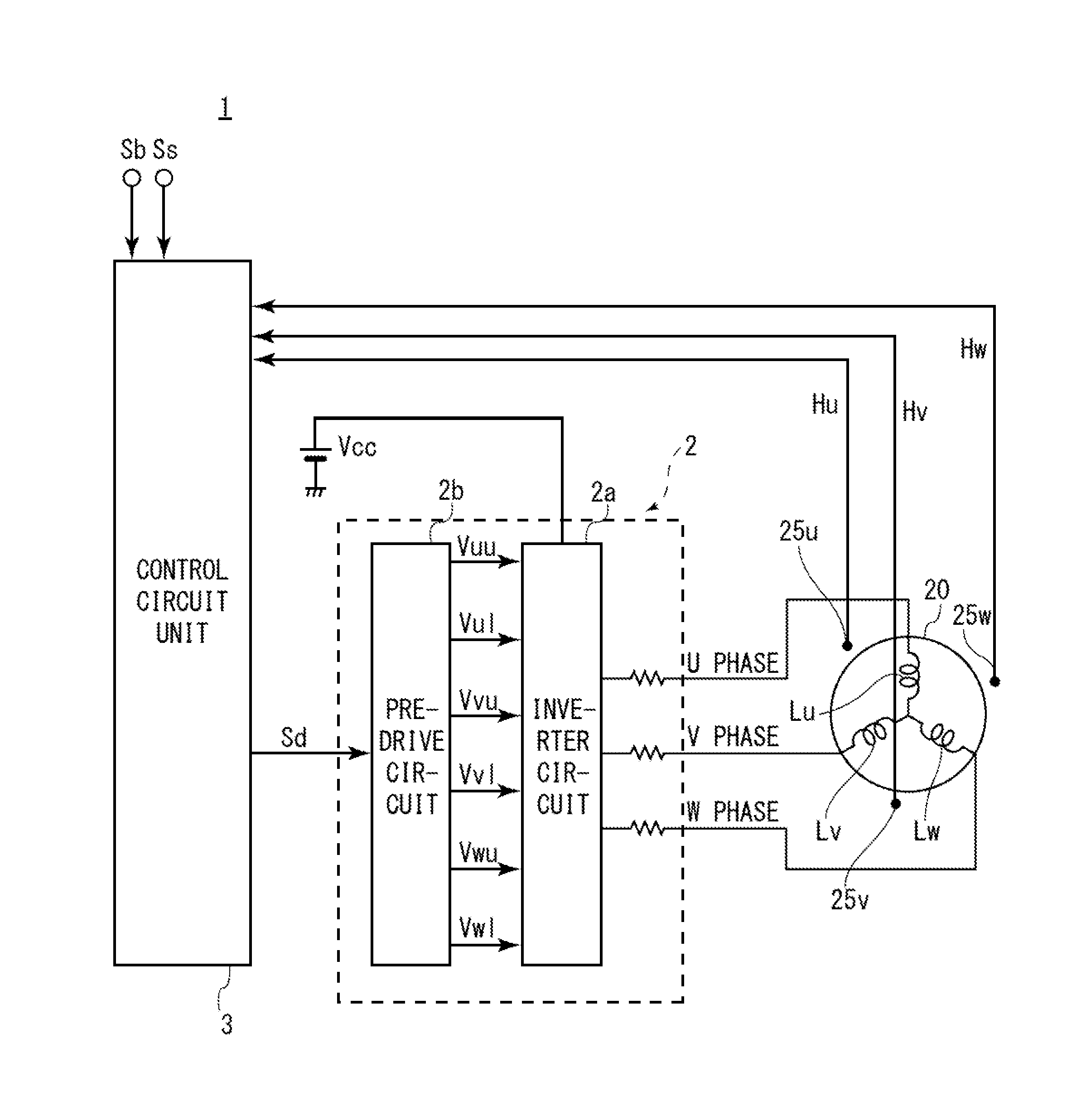
[0024]FIG. 1 is a diagram illustrating a circuit configuration of a motor drive controller 1 according to a first embodiment of the invention.

[0025]As illustrated in FIG. 1, the motor drive controller 1 is configured to drive a brushless motor 20 (hereinafter, simply referred to as a motor 20), for example, by sine wave drive. In this embodiment, the motor 20 is, for example, a three-phase brushless motor. The motor drive controller 1 rotates the motor 20 by outputting a sine-wave drive signal to the motor 20 to cause a sinusoidal drive current to periodically flow in armature coils Lu, Lv, and Lw of the motor 20.

[0026]The motor drive controller 1 is provided with a motor drive unit 2 including an inverter circuit 2a and a pre-drive circuit 2b and a control circuit unit 3. The components of the motor drive controller 1 illustrated in FIG. 1 may be only a part of the motor drive controller 1, and the motor drive controller 1 may further be provided with other components in addition t...

second embodiment

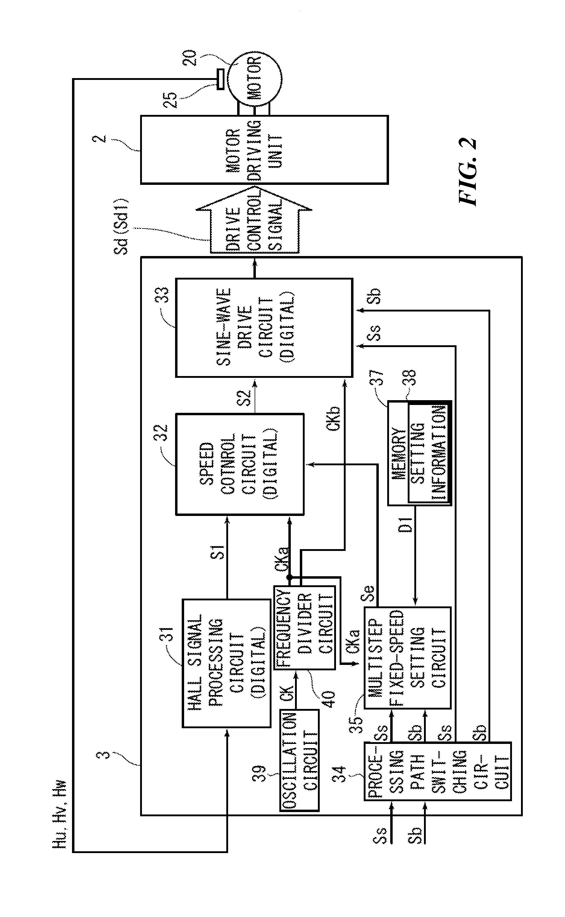
[0106]A basic configuration of a motor drive controller according to a second embodiment may be the same as that of the first embodiment and description for the similar parts and operation thereof will not be repeated. The second embodiment is different from the first embodiment, in that a signal path through which a rotation speed command signal is input from the outside in addition to the step command signal is formed.

[0107]FIG. 7 is a diagram illustrating a circuit configuration of a motor drive controller 101 according to the second embodiment of the invention.

[0108]As illustrated in FIG. 7, in the motor drive controller 101, a control circuit unit 103 having a slightly different configuration is formed instead of the control circuit unit 3 of the first embodiment. In the control circuit unit 103, a signal path through which a rotation speed command signal Sc is input is formed in addition to the signal path through which the start signal Ss and the brake signal Sb (or the step ...


PUM


Abstract

A motor drive controller includes: a control circuit unit configured to output a drive control signal for driving a motor in response to a command signal externally input to the control circuit unit; and a motor driving unit configured to output a drive signal to the motor based on the drive control signal output from the control circuit unit. The control circuit unit is provided with: a speed setting unit configured to generate a target rotation speed signal corresponding to a target rotation speed based on a command step determined in response to a step command signal and predetermined setting information when the step command signal is input as the command signal; and a drive control signal generating unit configured to generate and output the drive control signal based on the target rotation speed signal.

Description

BACKGROUND OF THE INVENTION[0001]1. Field of the Invention[0002]The present invention relates to a motor drive controller and a control method of the motor drive controller, and more particularly, to a motor drive controller that controls a rotation speed of a motor based on an external input signal and a control method of the motor drive controller.[0003]2. Description of the Related Art[0004]A method of controlling a rotation speed of a motor (for example, a brushless DC motor which is used as a fan motor or a motor of an electric fan) using a motor drive controller is known in which an external command signal is input and the rotation speed of the motor is controlled based on the command signal. An example of the command signal is a pulse-width modulation (PWM) signal and a rotation speed of a motor is controlled based on a duty ratio of the PWM signal.[0005]An example of such configuration is disclosed in JP-A-2014-036571. The publication JP-A-2014-036571 discloses a configurati...

Claims


Application Information

Patent Timeline
Patent Type & Authority Applications(United States)
IPC IPC(8): H02P6/08
CPCH02P6/08H02P6/06H02P6/085H02P25/024H02P1/46H02P1/52
Inventor KATAYAMA, KEIICHIINOUE, TOMOHIRO
Owner MINEBEAMITSUMI INC
Why Eureka
Try Eureka