Wireless network deployment method, apparatus and system

Inactive Publication Date: 2016-05-05
FUJITSU LTD
View PDF1 Cites 15 Cited by
  • Summary
  • Abstract
  • Description
  • Claims
  • Application Information

AI Technical Summary

Benefits of technology

[0033]An advantage of the embodiments of the present disclosure exists in that a deployment process of the wireless network is simulated as a dynamic physical process, movement of the access points along a direction of a resultant force of all repulsion forces and attractive forces is controlled following th

Problems solved by technology

How to provide high-quality wireless communication services to mobile equipment is a crucial problem.
Taking a WiFi network as an example, as its coverage is small, the manual deployment method can be used to build a home indoor wireless network, simple and convenient, but the manual deployment method is hard to satisfy the requirements of deploying the WiFi network in a range

Method used


Image

  • Wireless network deployment method, apparatus and system
  • Wireless network deployment method, apparatus and system
  • Wireless network deployment method, apparatus and system

Examples


embodiment 1

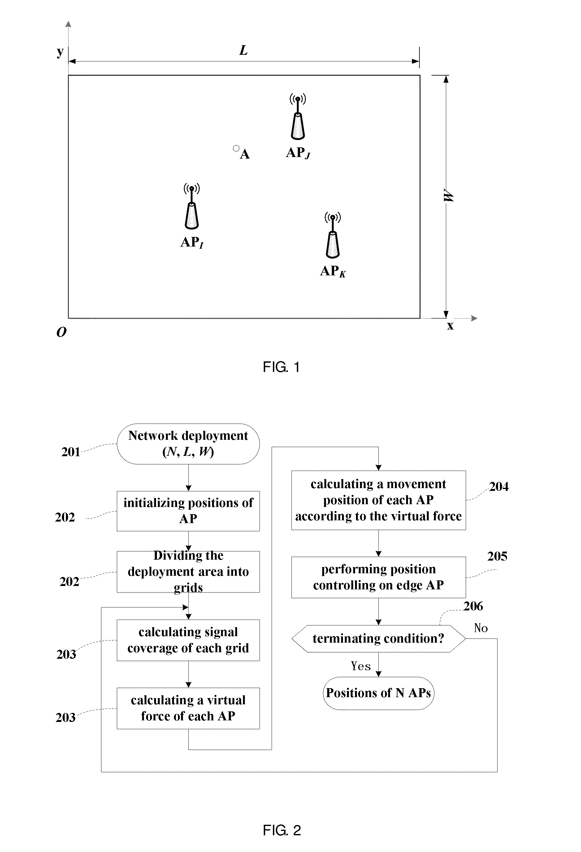
[0071]An embodiment of the present disclosure provides a wireless network deployment method. FIG. 2 is a flowchart of the method. Referring to FIG. 2, the method includes:

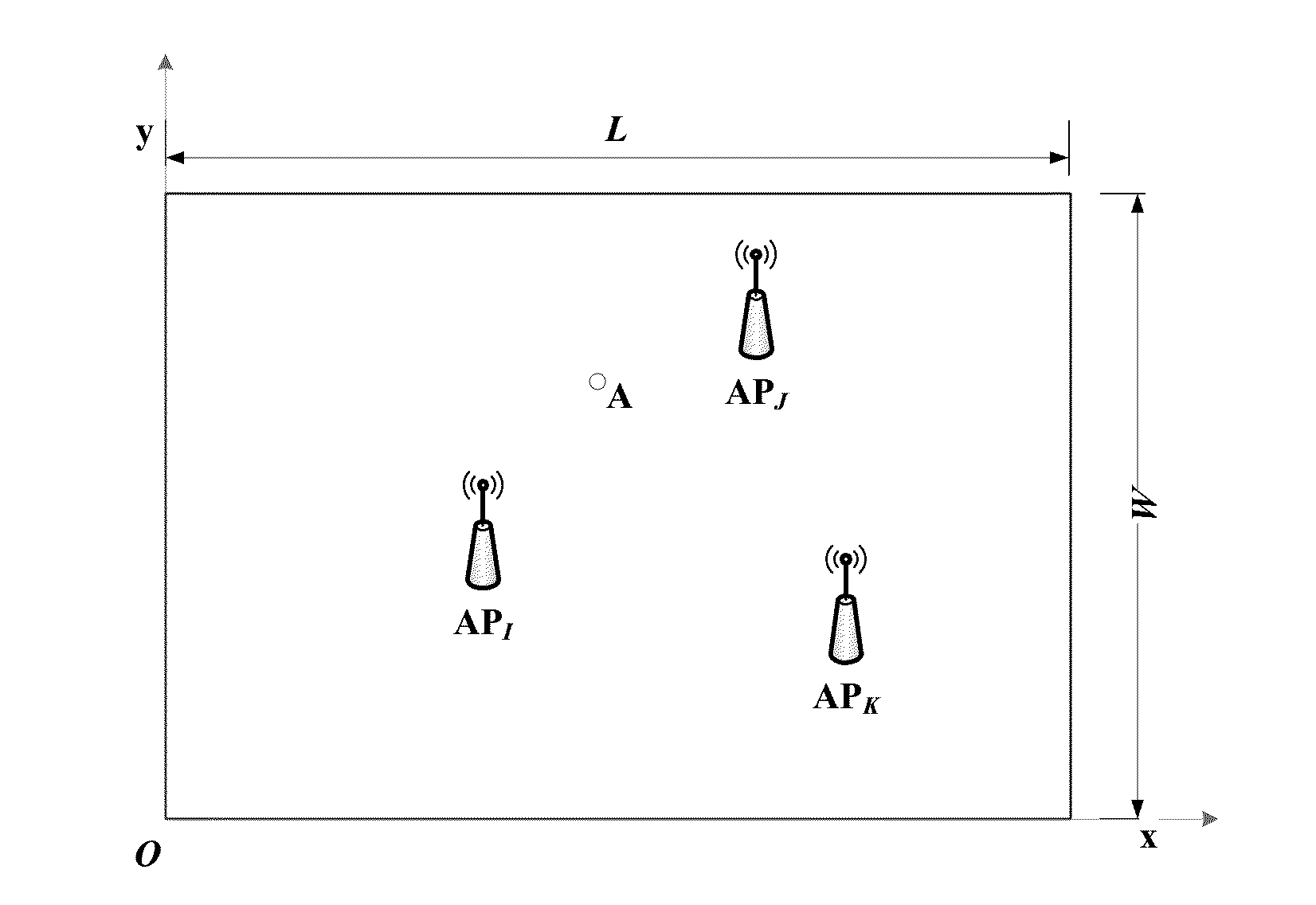
[0072]step 201: initializing the wireless network to determine a deployment area of the wireless network and the number of access points needing to be deployed;

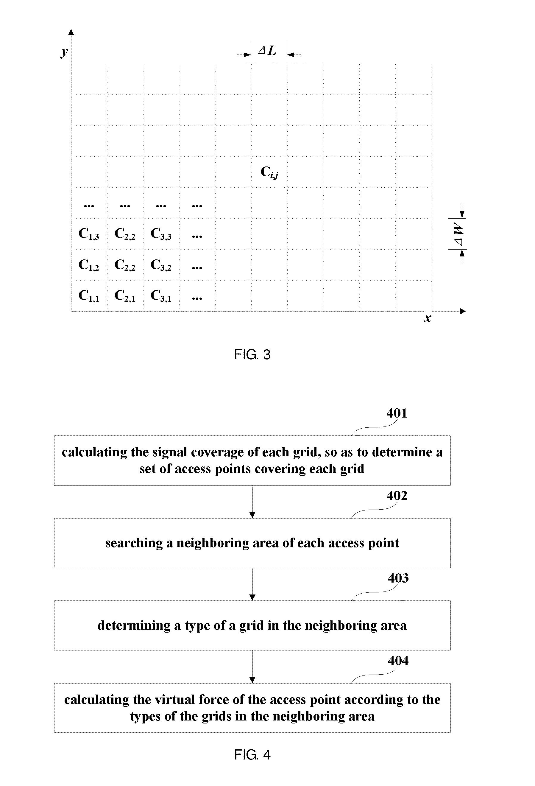
[0073]step 202: initializing positions of the access points, and dividing the deployment area into grids;

[0074]step 203: calculating a virtual force of each access point in the wireless network based on signal coverage of each grid;

[0075]step 204: calculating a movement position of each access point according to the virtual force of each access point;

[0076]step 205: performing edge controlling on each access point; and

[0077]step 206: terminating processing in case that a terminating condition is satisfied, so as to obtain a deployment result of the wireless network.

[0078]In step 201, in initializing the wireless network, the number N of access points needing...

embodiment 2

[0141]An embodiment of the present disclosure further provides a wireless network deployment apparatus. As principles of the apparatus for solving problems is similar to that of the method of Embodiment 1, the implementation of the method of Embodiment 1 may be referred to for the implementation of the apparatus, with identical parts being not going to be described herein any further.

[0142]FIG. 19 is a schematic diagram of a structure of the wireless network deployment apparatus of this embodiment. Referring to FIG. 19, the apparatus 1900 includes a first initializing unit 1901, a second initializing unit 1902, a first calculating unit 1903, a second calculating unit 1904, an edge controlling unit 1905 and a judging unit 1906; wherein,

[0143]the first initializing unit 1901 is configured to initialize the wireless network to determine a deployment area of the wireless network and the number of access points needing to be deployed;

[0144]the second initializing unit 1902 is configured ...

embodiment 3

[0170]An embodiment of the present disclosure further provides a computer system, including the wireless network deployment apparatus as described in Embodiment 2.

[0171]FIG. 25 is a schematic diagram of a structure of the computer system of this embodiment. As shown in FIG. 25, the computer system 2500 may include a central processing unit (CPU) 2501 and a memory 2502, the memory 2502 being coupled to the central processing unit 2501. The memory 2502 may store various data, and furthermore, store programs for information processing, and execute the programs under control of the central processing unit 2501.

[0172]In an implementation, the functions of the wireless network deployment apparatus described in Embodiment 2 may be integrated into the central processing unit 2501. In this implementation, the central processing unit 2501 may be configured to initialize the wireless network to determine a deployment area of the wireless network and the number of access points needing to be de...


PUM


Abstract

A wireless network deployment method, apparatus and system where the includes: initializing the wireless network to determine a deployment area and the number of access points needing to be deployed; initializing positions of the access points, and dividing the deployment area into grids; calculating a virtual force of each access point based on signal coverage of each grid; calculating a movement position of each point according to the virtual force; performing edge controlling on each point; and terminating processing when a terminating condition is satisfied. A deployment process is simulated as a dynamic physical process, movement of the access points along a direction of a resultant force of all repulsion forces and attractive forces is controlled following the principle that an overlapping covered area produces a repulsion force and an uncovered area produces an attractive force.

Description

CROSS-REFERENCE TO RELATED APPLICATIONS[0001]This application claims the benefit of Chinese Application No. 201410602422.6, filed Oct. 31, 2014, the disclosure of which is incorporated herein by reference.BACKGROUND[0002]1. Field[0003]The present disclosure relates to the field of communication technologies, and in particular to a wireless network deployment method, apparatus and system.[0004]2. Description of the Related Art[0005]Currently, various mobile equipment emerges endlessly, such as a notebook computer, a tablet computer, a smart mobile phone, a wearable device, and a smart sensor, etc. The market of mobile equipment is also booming, and many users have multiple different or identical types of mobile equipment. Wireless communication is one of the core functions of the mobile equipment. There are a variety of wireless communication networks, such as a cellular network, a WiFi network, and a Bluetooth network, etc., which are supported by much mobile equipment. In the above...

Claims


Application Information

Patent Timeline
IPC IPC(8): H04W16/18
CPCH04W16/18
Inventor LI, HONGCHUNTIAN, JUN
Owner FUJITSU LTD
Why Eureka
Try Eureka