Pneumatic tire

a technology of pneumatic tires and tires, applied in the field of pneumatic tires, can solve the problems of deteriorating tire traction, neither of these pneumatic tires taken into account a point of easy discharging, etc., and achieve the effect of further improving the mud discharging property

Active Publication Date: 2016-05-12
TOYO TIRE & RUBBER CO LTD
View PDF7 Cites 15 Cited by
  • Summary
  • Abstract
  • Description
  • Claims
  • Application Information

AI Technical Summary

Benefits of technology

[0021]With such a configuration, mud discharging property can be further improved.
[0022]According to the present invention, a plurality of projections are formed in the side portion and hence, when a tire chain is mounted on the tire, the tire chain is brought into contact with the projections whereby t...

Problems solved by technology

Further, when a vehicle travels on a bad road, mud or the like intrudes into grooves formed in the projection.
When a state where mud intrudes into the groove or the like is kept, tract...

Method used


Image

  • Pneumatic tire
  • Pneumatic tire
  • Pneumatic tire

Examples


Embodiment Construction

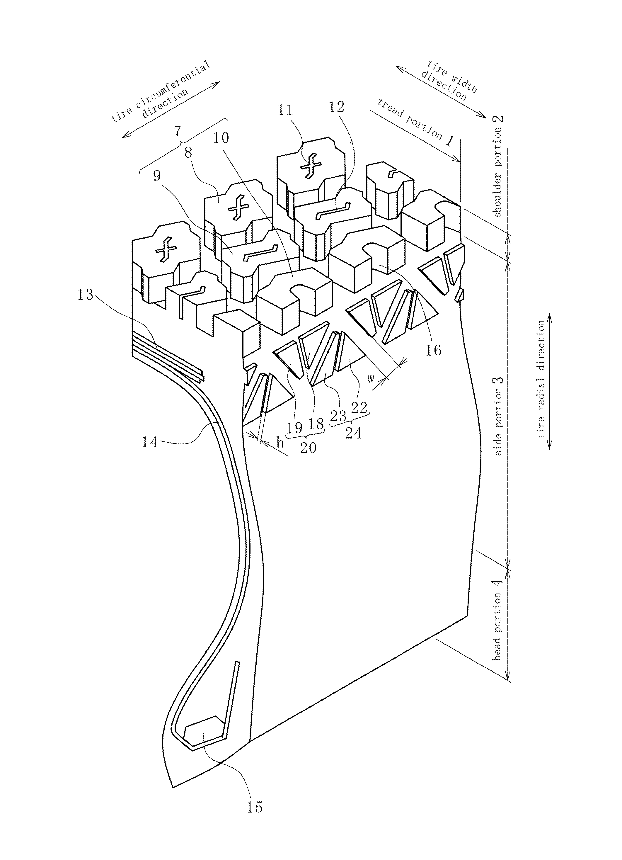
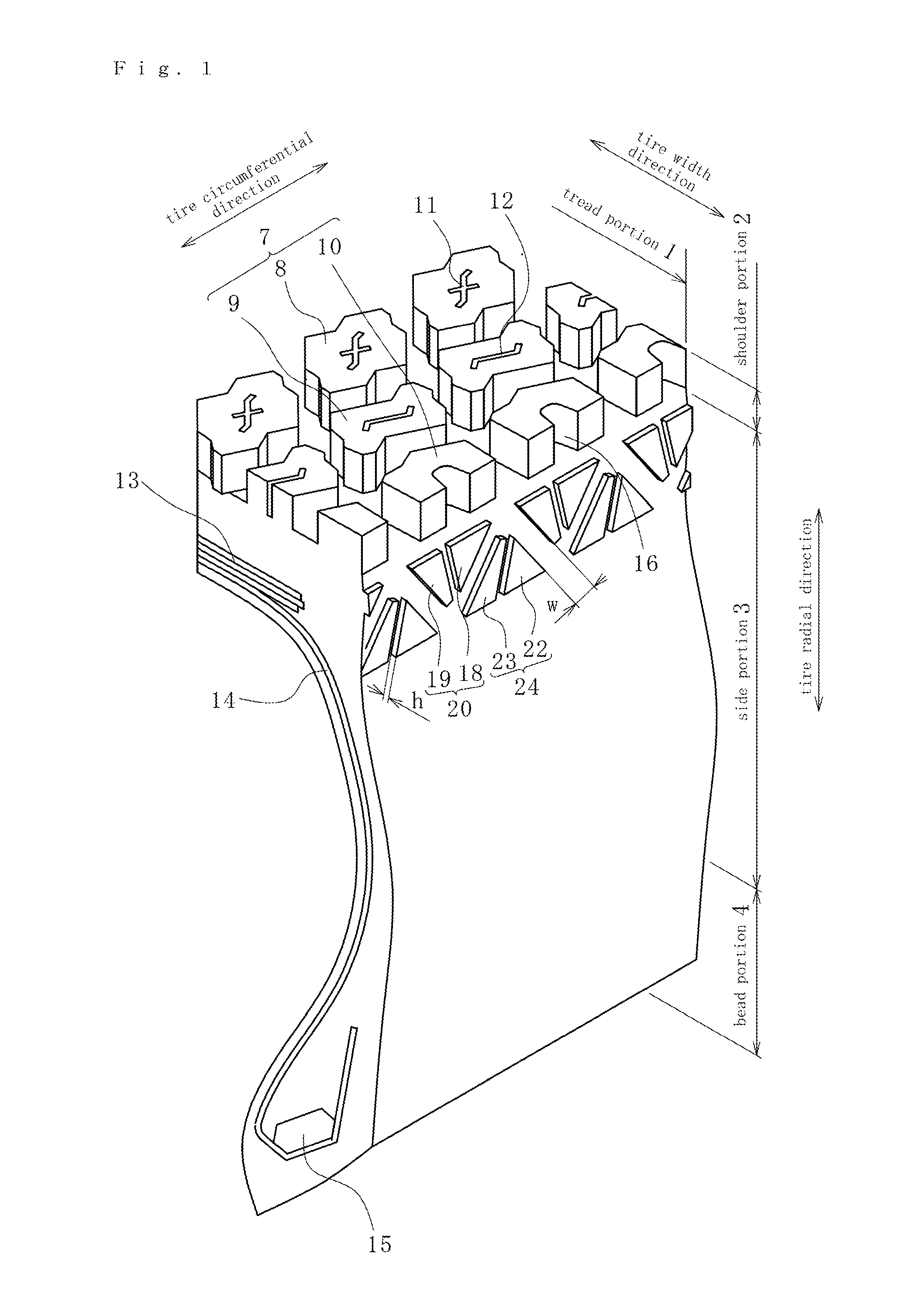
[0027]Hereinafter, embodiments of the present invention are described by reference to attached drawings. The description made hereinafter merely shows an example essentially, and does not intend to limit the present invention, products to which the present invention is applied, or its applications. Further, drawings are schematically shown and hence, ratios of respective sizes and the like may differ from actual ratios of sizes and the like.

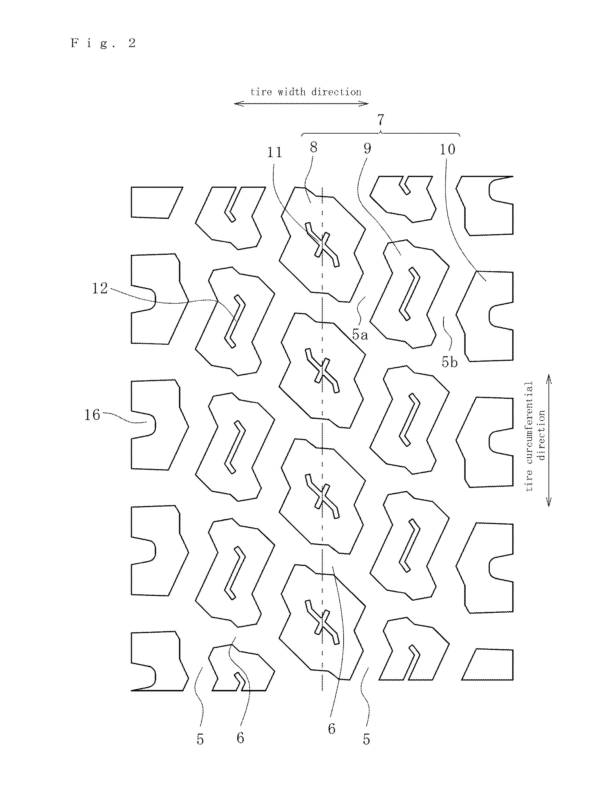
[0028]FIG. 1 is a cross-sectional perspective view showing a portion of a pneumatic tire according to this embodiment. The pneumatic tire has the outer structure constituted of a tread portion 1, shoulder portions side portions 3 and bead portions 4. The tread portion 1 has a brock pattern where a plurality of blocks 7 are formed by four main grooves 5 which extend in the tire circumferential direction in a zigzag manner and a plurality of lateral grooves 6 (lug grooves) which intersect with the main grooves 5 and extend in the tire width directi...


PUM


Abstract

Provided is a pneumatic tire being excellent in property of protecting the tire from a mounted tire chain or being excellent in property of discharging mud from grooves formed on the tire.
The pneumatic tire includes a tread portion having lug grooves, and side portions which are contiguously formed with the tread portion. Projections which differ in at least one of a shape and a size are arranged on a side portion in a plurality of rows in a tire radial direction. Opening positions of small lug grooves on both sides of the tread portion are made to agree with a straight line which passes the projection and extends in the tire radial direction.

Description

CROSS-REFERENCE TO RELATED APPLICATIONS[0001]This application claims priority from Japanese Patent Application No. 2014-228990, the disclosure of which is incorporated herein by reference in their entireties.BACKGROUND OF THE INVENTION[0002]1. Field of the Invention[0003]The present invention relates to a pneumatic tire.[0004]2. Description of Related Art[0005]Conventionally, as a pneumatic tire, there has been known a pneumatic tire where protect bars are formed on an outer surface of a side portion in a projecting manner along a circumferential direction of the tire, and inclined grooves which are inclined in directions opposite to each other with respect to a tire radial direction are alternately formed on the protect bars at intervals in the tire circumferential direction (see Japanese patent 4367869, for example).[0006]Further, as another pneumatic tire, there has been known a pneumatic tire where a plurality of projections are formed on a buttress portion along a tire circumfe...

Claims


Application Information

Patent Timeline
IPC IPC(8): B60C13/02B60C11/03
CPCB60C13/02B60C2011/0339B60C11/0306B60C11/11B60C11/01B60C13/002B60C2200/14
Inventor FUJIOKA, TSUYOSHI
Owner TOYO TIRE & RUBBER CO LTD
Why Eureka
Try Eureka