
An electrical protection device and a method of providing electrical protection

a technology of electrical protection device and protection device, which is applied in the direction of emergency protection arrangement for limiting excess voltage/current, short-circuit testing, instruments, etc., can solve the problems of rcd not providing adequate protection, many technology deficiencies, and easy to be triggered by false triggers

Active Publication Date: 2016-05-12
IEP2 RES PTY
View PDF0 Cites 11 Cited by
  • Summary
  • Abstract
  • Description
  • Claims
  • Application Information

AI Technical Summary

Benefits of technology

The patent describes a switching unit that can protect the load current from overcurrent or short-circuiting. The unit can automatically disconnect the input terminals from the output terminals when a fault is detected, and reconnect them when the fault is cleared. This helps to prevent damage to the load and ensures safe use of the power source.

Problems solved by technology

However at the same time many deficiencies in the technology have become apparent.
In particular it is being increasingly recognised that there are many circumstances where an RCD will not provide adequate protection, or where it will be susceptible to false triggers.
However, this technology is not readily applicable to MEN systems in light of the method of operation and the difficulties in achieving compliance with the required standards for protection circuits.
A high (non-critical) fault impedance may still result in a significant voltage on the chassis.
However, such a voltage may not be capable of delivering sufficient current to cause harm.
In such cases voltage sensing or current sensing technologies may clearly see a fault signal.
However, current leakage technology requires positive and significant fault current flow before it generates any fault indication.
Consequently, in a well-maintained MEN (TN) system, chassis or electrical metal work sensing may not provide a reliable fault signal.
Notwithstanding better performance than either of the earlier technologies many practical problems remain in gaining reliable and widespread use of such devices.
These problems include:A susceptibility to fault triggering as a result of electrical disturbances such as lighting and power line transients.

Method used


Image

  • An electrical protection device and a method of providing electrical protection
  • An electrical protection device and a method of providing electrical protection
  • An electrical protection device and a method of providing electrical protection

Examples


Embodiment Construction

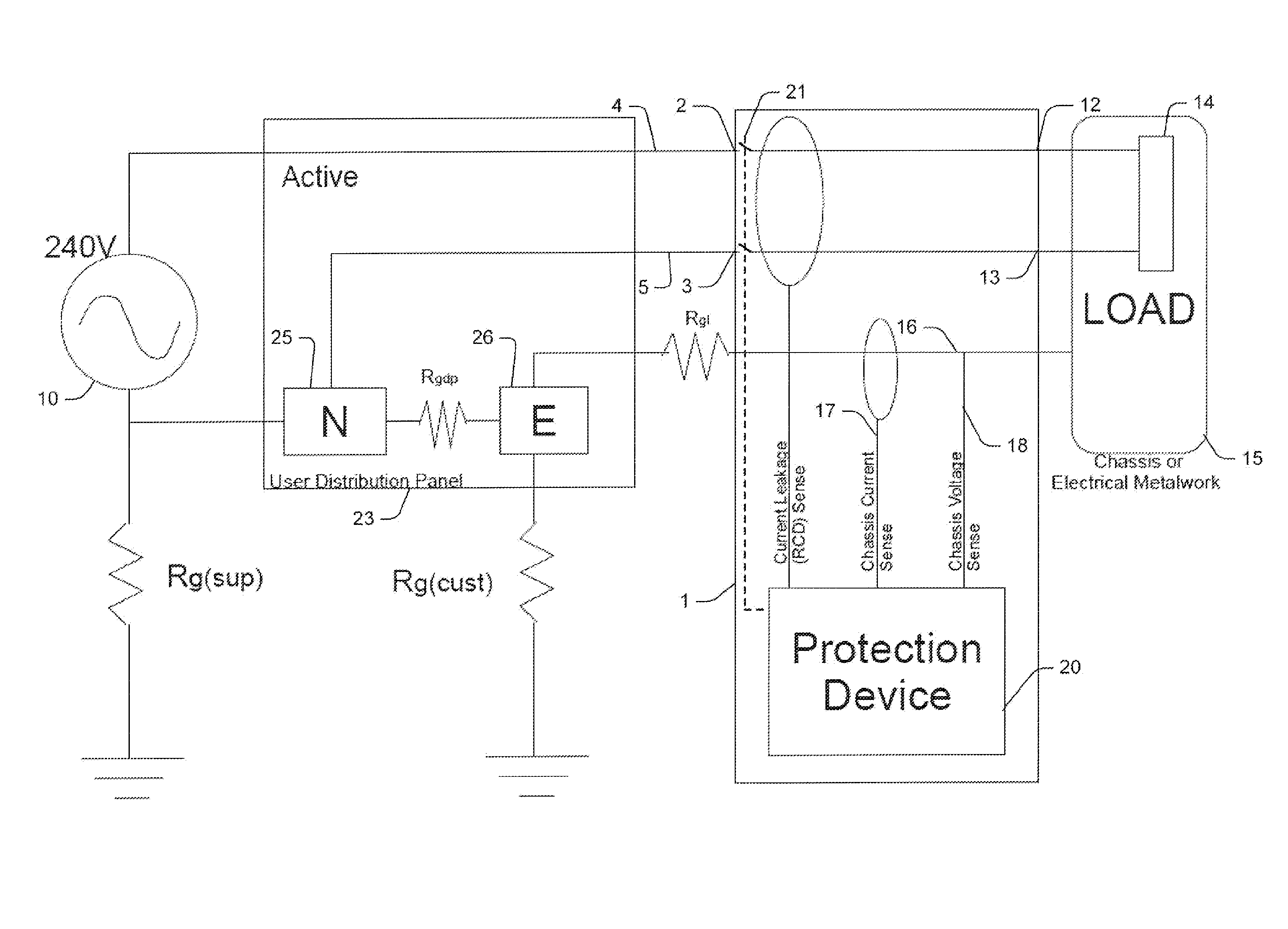
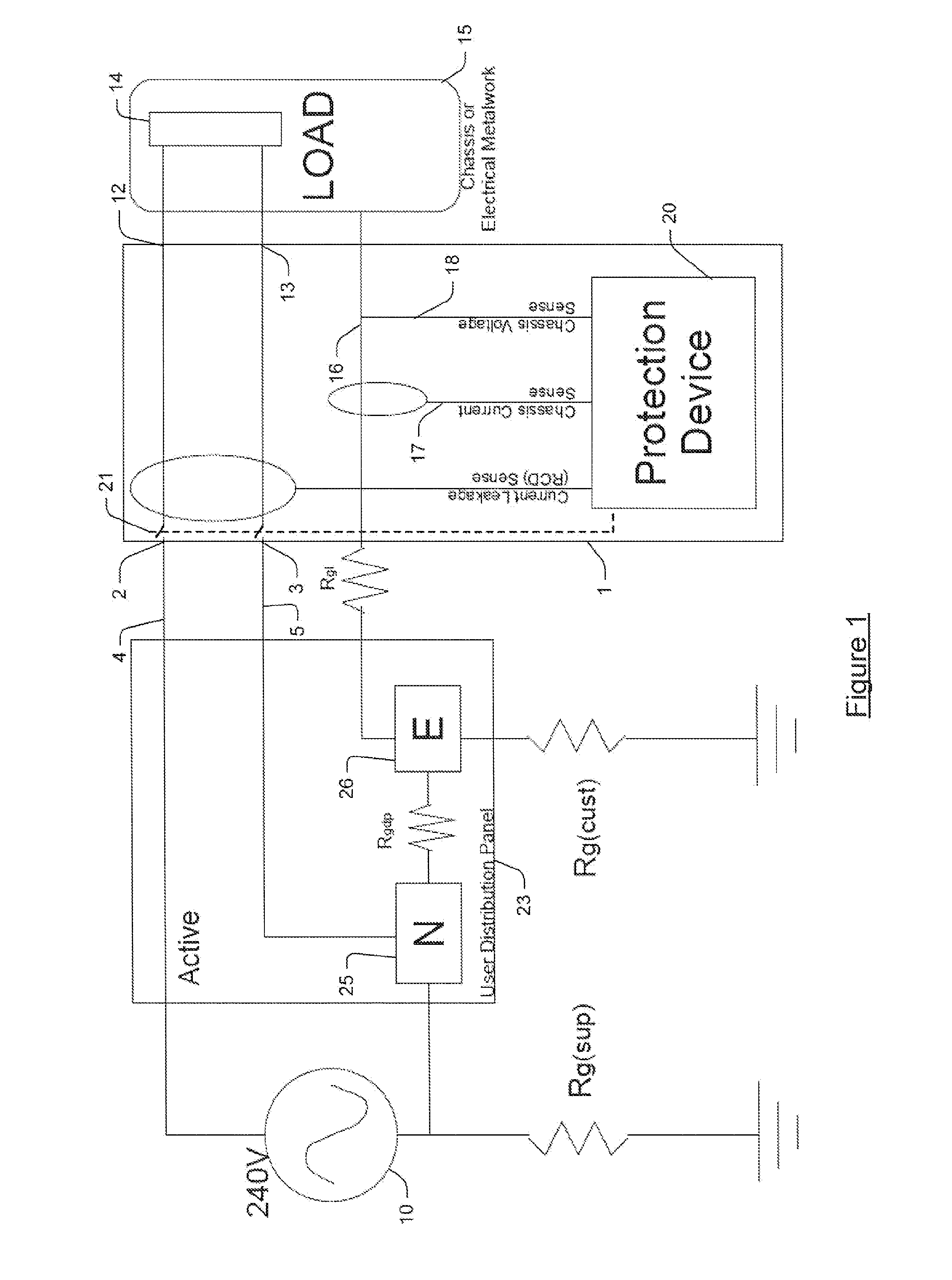
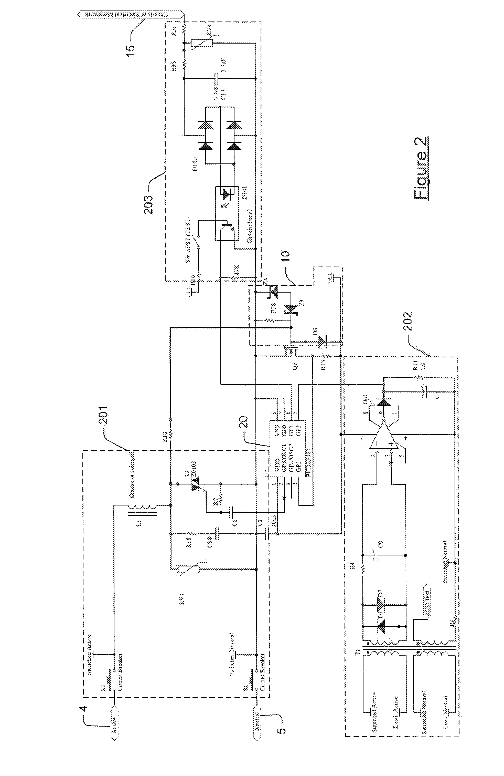
[0185]Referring initially to FIG. 1, an electrical protection device 1 includes two input terminals 2 and 3 for electrically connecting respectively to an active conductor 4 and a neutral conductor 5 of an electrical power source 10 that is upstream of device 1. Device 1 further includes two output terminals 12 and 13 for electrically connecting to a load 14 having a conductive metal chassis 15 (or electric metal work or casing) that is downstream of device 1. Load 14 draws a load current at a load voltage. Device 1 includes a first sensor for providing a first signal derived from the load current, specifically the leakage current from the load. Furthermore, device 1 includes a second sensor for providing a second signal derived from the voltage on chassis 15, specifically a current in chassis 15 and a voltage on chassis 15. Furthermore, device 1 includes a processing unit in the form of a microprocessor 20 is responsive to the first and second signals for selectively generating a f...


PUM


Abstract

There is provided an integration of the leakage current functions of an RCD and the voltage sensing functions of other prior art protection devices. By integrating the two capabilities into one decision making system / algorithm, and considering the circuits performance in terms of leakage current as it correlated with elevated protective earth voltages (and vice versa), an embodiment is created which is able to “look into” a protected electrical system and make much more precise and discerning decisions on electrical status and probability of unsafe events. The resultant technology attends to the outstanding issues with the prior art technologies as they stand, and provides a protection solution that covers the entire range of electrical power wiring configurations and the practical complexities of modern electrical works.

Description

FIELD OF THE INVENTION[0001]The present invention relates to an electrical protection device and a method of providing electrical protection.[0002]Embodiments of the invention have been particularly developed as residual current devices (RCDs) for use in mains power distribution and will be described herein with particular reference to that application. However, it will be appreciated that the invention is not limited to such a field of use, and is applicable in broader contexts.BACKGROUND[0003]Any discussion of the background art throughout the specification should in no way be considered as an admission that such art is widely known or forms part of common general knowledge in the field.[0004]RCD protection technology was invented around the 1960's to provide a tertiary level of electrical protection against electrocution. RCD technology reacts to leakage of current from an electrical circuit to implement a protective function should that leakage current exceeds a level that is de...

Claims


Application Information

Patent Timeline
IPC IPC(8): H02H9/04G01R31/02
CPCG01R31/025H02H9/04G01R31/52H02H3/14H02H3/16H02H3/33
Inventor HARRIS, RICHARDRUBYTHON, GEOFFREY
Owner IEP2 RES PTY
Learn More