Nozzle and substrate processing apparatus using same

Active Publication Date: 2016-05-19
TOKYO ELECTRON LTD
View PDF4 Cites 1 Cited by
  • Summary
  • Abstract
  • Description
  • Claims
  • Application Information

AI Technical Summary

Benefits of technology

[0012]Accordingly, embodiments of the present invention may provide a nozzle and a substrate processing appa

Problems solved by technology

Accordingly, when base portions of the gas nozzles are fixed to the side wall of the process chamber, the moment of tip portions of the gas nozzles become great, which causes the tip portions to be likely to descend due to its own weight.
This causes a problem of making density of the reaction gases lower in the central area than in the peripheral area.
Gas species for film deposition used in the high-k processes have caused a problem of deteriorating film properties because the gas species have such poor resistance properties as source gases that the gas species cannot sustain the same condition in a high temperature in the process chamber as the condition in a low temperature, and further because self-decomposition of the gas species occurs in a gas phase before adsorbing on a wafer.
More speci

Method used


Image

  • Nozzle and substrate processing apparatus using same
  • Nozzle and substrate processing apparatus using same
  • Nozzle and substrate processing apparatus using same

Examples


Embodiment Construction

[0025]A description is given below of embodiments of the present invention with reference to accompanying drawings.

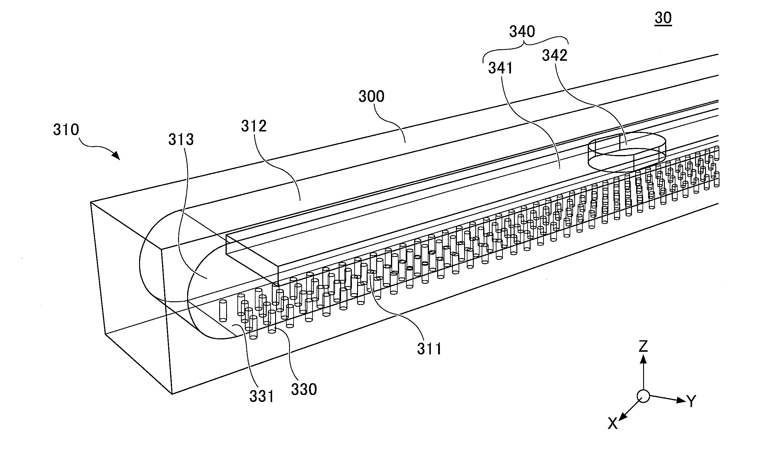
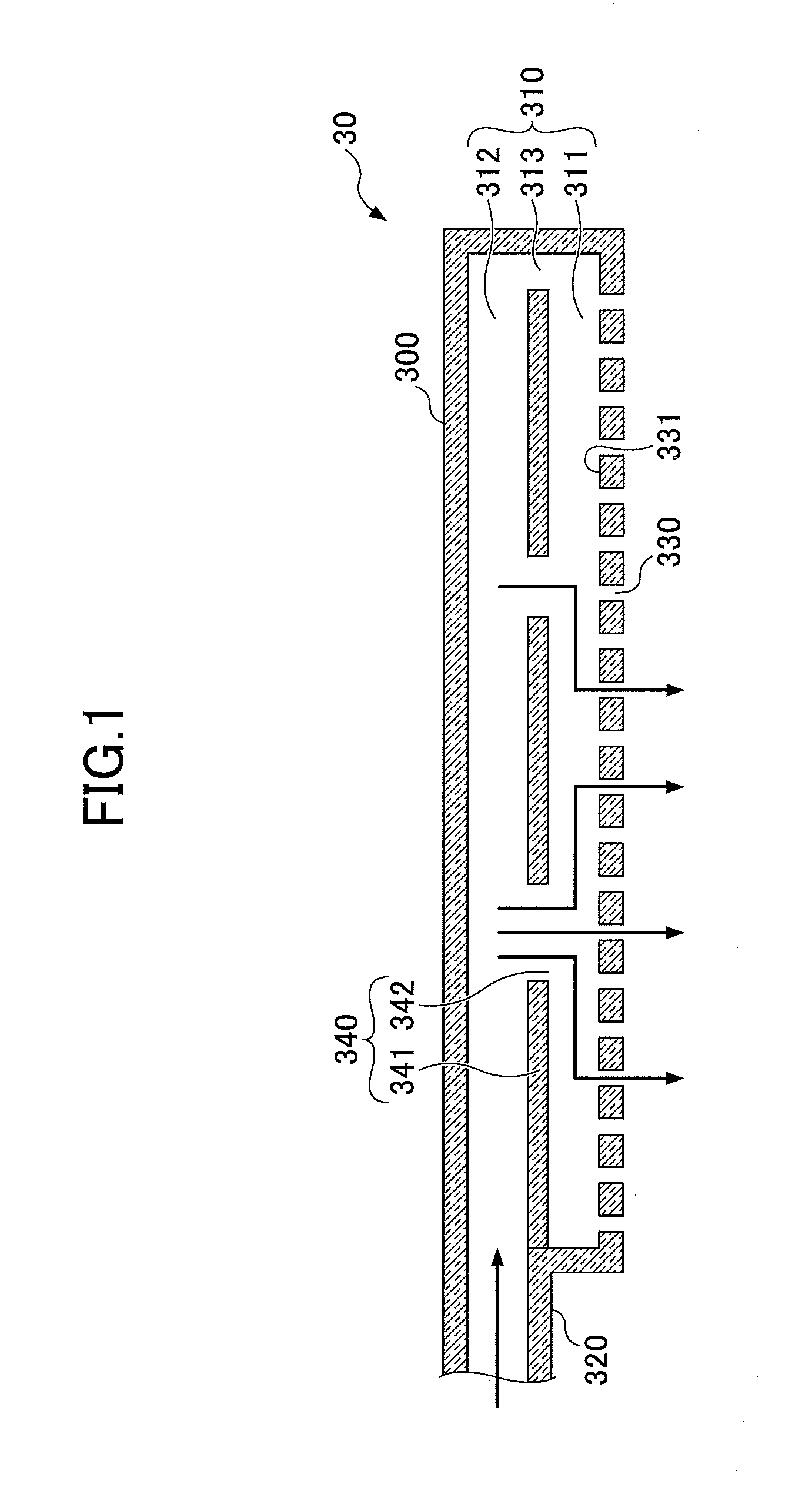
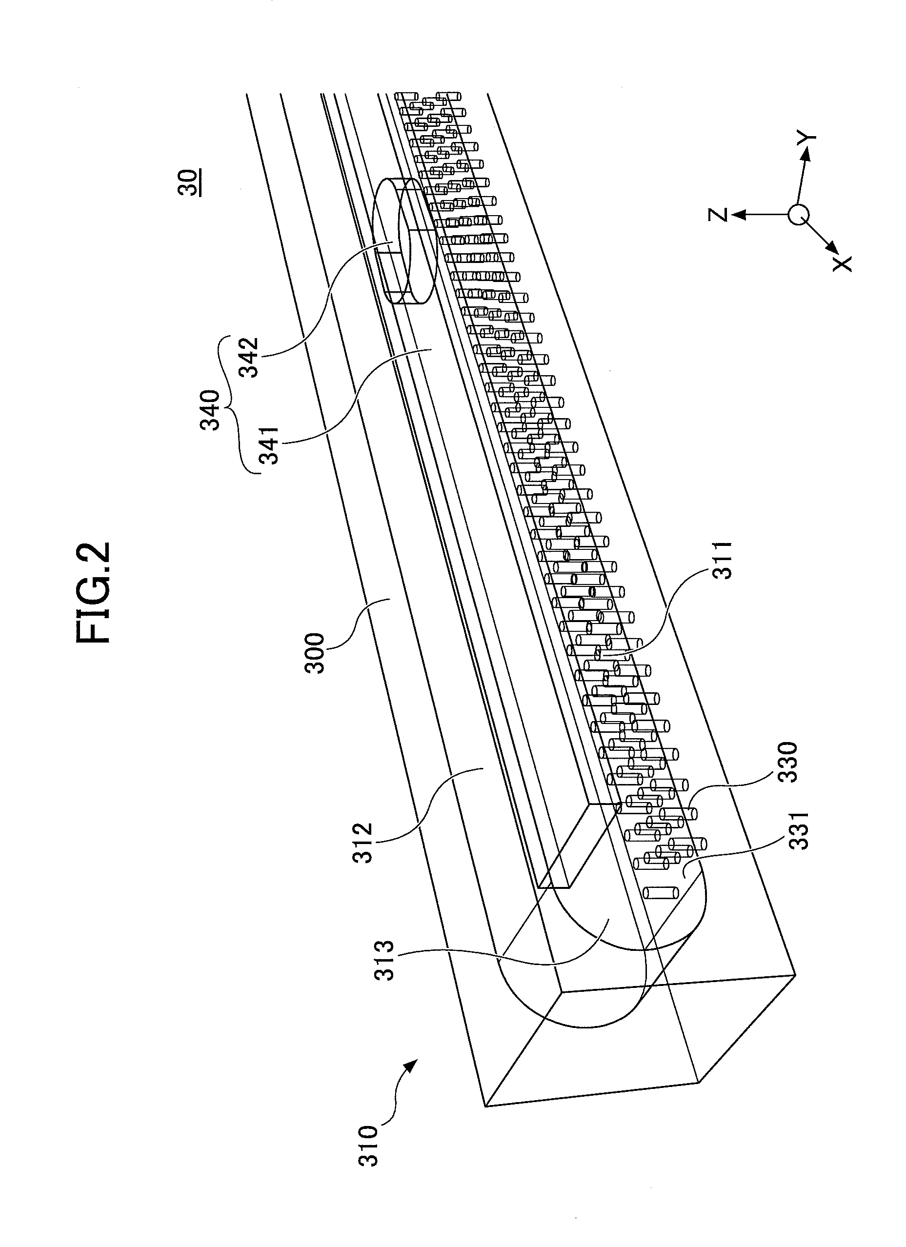
[0026]FIG. 1 is a cross-sectional view illustrating a configuration of an example of a nozzle according to an embodiment of the present invention. A nozzle 30 of the embodiment of the present invention includes a tubular part 300, a tubular passage 310, a fluid introduction passage 320, fluid discharge holes 330, and a partition plate 340. The tubular part 300 includes the tubular passage 310 thereinside, and the fluid discharge hole 330 is formed in a lower surface of the tubular passage 310. The partition plate 340 is provided between an upper surface and the lower surface inside the tubular passage 310. The partition plate 340 partitions the tubular passage 310 into a fluid discharge area 311 including a fluid discharge surface 311 in which the fluid discharge holes 330 are formed, and a fluid flow area 312 without a surface in which the fluid discharge holes 330 is ...


PUM

PropertyMeasurementUnit
Dielectric polarization enthalpyaaaaaaaaaa
Flow rateaaaaaaaaaa
Diameteraaaaaaaaaa

Abstract

A nozzle for supplying a fluid includes a tubular part including a tubular passage thereinside and a fluid discharge surface having a plurality of fluid discharge holes formed therein along a lengthwise direction of the tubular passage. A partition plate is provided in the tubular passage and extends along the lengthwise direction so as to partition the tubular passage into a first area including the fluid discharge surface and a second area without the fluid discharge surface. The partition plate has distribution holes whose number is less than a number of the plurality of fluid discharge holes in the lengthwise direction. A fluid introduction passage is in communication with the second area.

Description

CROSS-REFERENCE TO RELATED APPLICATION[0001]The present application is based upon and claims the benefit of priority of Japanese Patent Application No. 2014-234500, filed on Nov. 19, 2014, the entire contents of which are incorporated herein by reference.BACKGROUND OF THE INVENTION[0002]1. Field of the Invention[0003]The present invention relates to a nozzle and a substrate processing apparatus using the same.[0004]2. Description of the Related Art[0005]Conventionally, the following process is known as a film deposition method in a semiconductor manufacturing process. In the process, one or more atomic layers or molecular layers are formed on a surface of a substrate such as a semiconductor wafer (which is hereinafter referred to as just a “wafer”) by causing a first reaction gas to adsorb on the surface of the wafer and then by switching a supplying gas from the first reaction gas to a second reaction gas to react with the first reaction gas on the surface of the wafer in a vacuum ...

Claims


Application Information

Patent Timeline
IPC IPC(8): C23C16/455B05B1/20
CPCB05B1/20C23C16/45563C23C16/45578C23C16/45591H01J37/3244C23C16/45587C23C16/45551B05B1/205
Inventor WAMURA, YUHAYASE, FUMIAKIKAMINISHI, MASAHIKOTAKAHASHI, KOSUKESASAKI, HIROKOSASAKI, YU
Owner TOKYO ELECTRON LTD
Why Eureka
Try Eureka