Diaphragm device and optical instrument

a diaphragm device and optical instrument technology, applied in the direction of camera diaphragms, instruments, cameras, etc., can solve the problem of increasing the thickness of the diaphragm device in the direction of the optical axis corresponding to the size of the provided partition plate, and achieve the effect of reducing the thickness of the diaphragm device and the optical instrumen

Active Publication Date: 2016-05-19
SEIKO HLDG KK TRADING AS SEIKO HLDG CORP
View PDF11 Cites 7 Cited by
  • Summary
  • Abstract
  • Description
  • Claims
  • Application Information

AI Technical Summary

Benefits of technology

[0023]By employing the above-described structure, it is possible to provide a small-sized optical instrument.
[0024]According to the present invention, it is possible to prevent first blades and second blades from obstructing each other during an opening or closing operation. Because of this, there is no need to provide a device in order to separate the first blades and the second blades, and the thickness of the diaphragm device and the optical instrument can be reduced.

Problems solved by technology

However, in the above-described conventional technology the problem arises that the size of the diaphragm device in its thickness direction (i.e., in the direction of the optical axis) is increased correspondingly to the size of the provided partition plate.

Method used


Image

  • Diaphragm device and optical instrument
  • Diaphragm device and optical instrument
  • Diaphragm device and optical instrument

Examples


first embodiment

[0036](Optical Instrument)

[0037]Firstly, a first embodiment of this invention will be described based on FIG. 1 through FIG. 7.

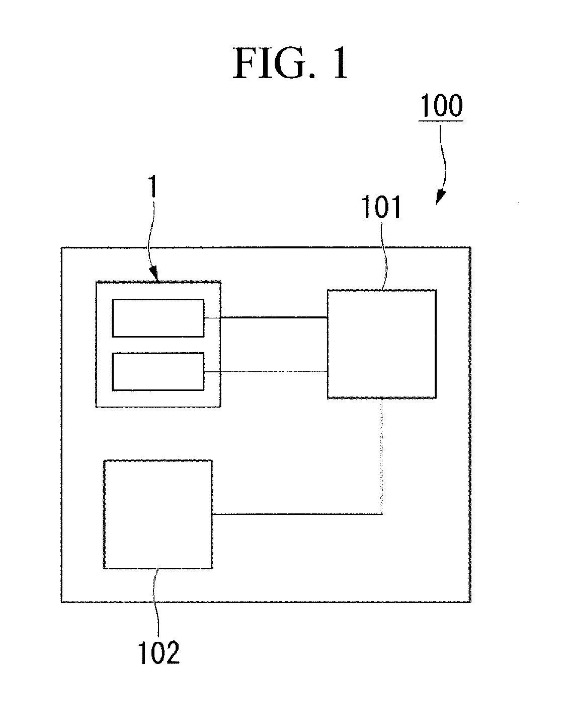
[0038]FIG. 1 is a block diagram of an optical instrument 100.

[0039]As is shown in FIG. 1, the optical instrument 100 is used, for example, as a digital camera or still camera, and is provided with a diaphragm device 1, a control unit 102, and an imaging element 103.

[0040]The control unit 102 manages the overall operation of the optical instrument 100, and is provided with a CPU, ROM, RAM, and the like.

[0041]The imaging element 103 is, for example, a CCD or CMOS, and converts object images that are formed by light into electrical signals.

[0042]Note that, although omitted from FIG. 1, the optical instrument 100 is also provided with a lens or the like that is used to adjust focal length.

[0043](Diaphragm Device)

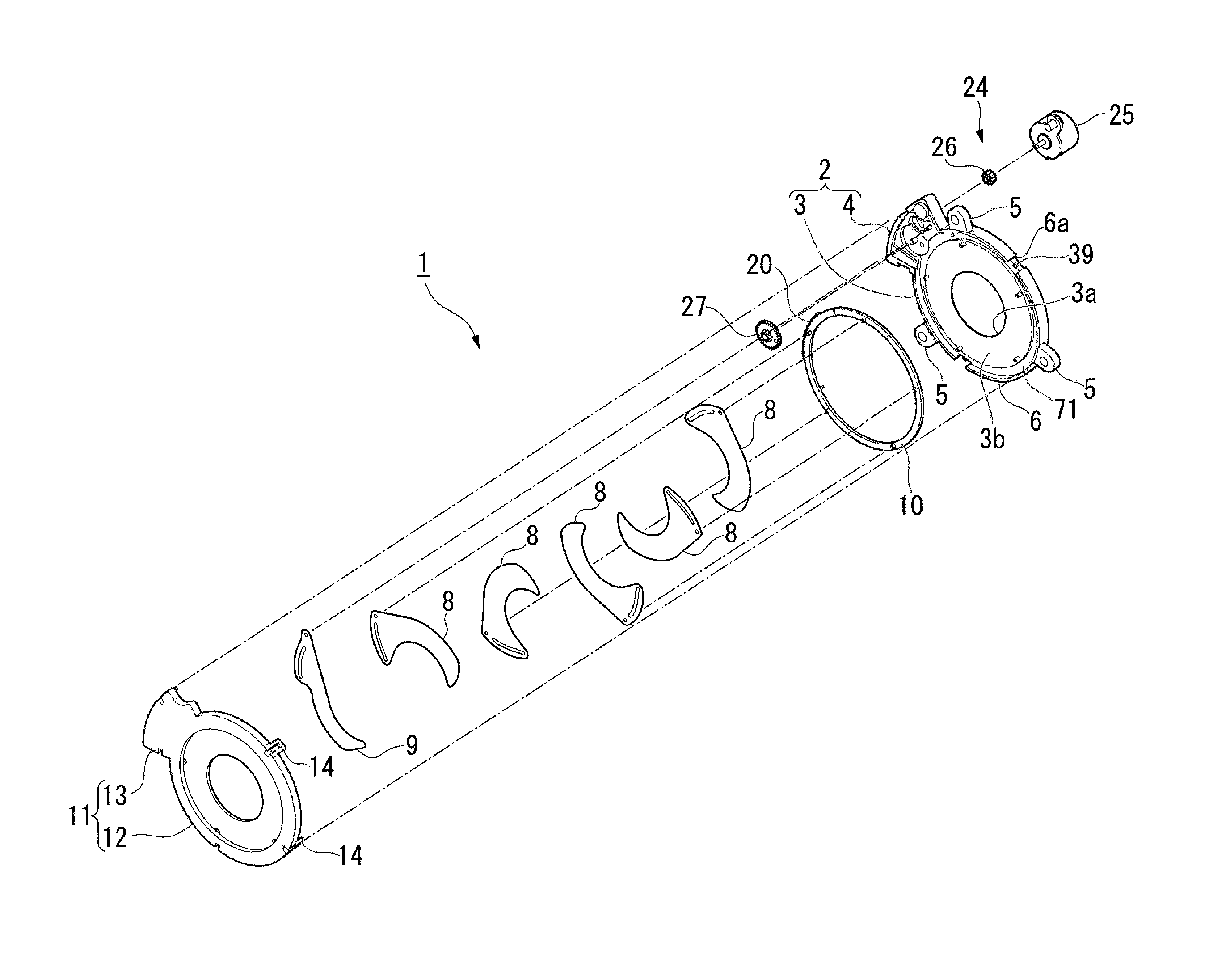
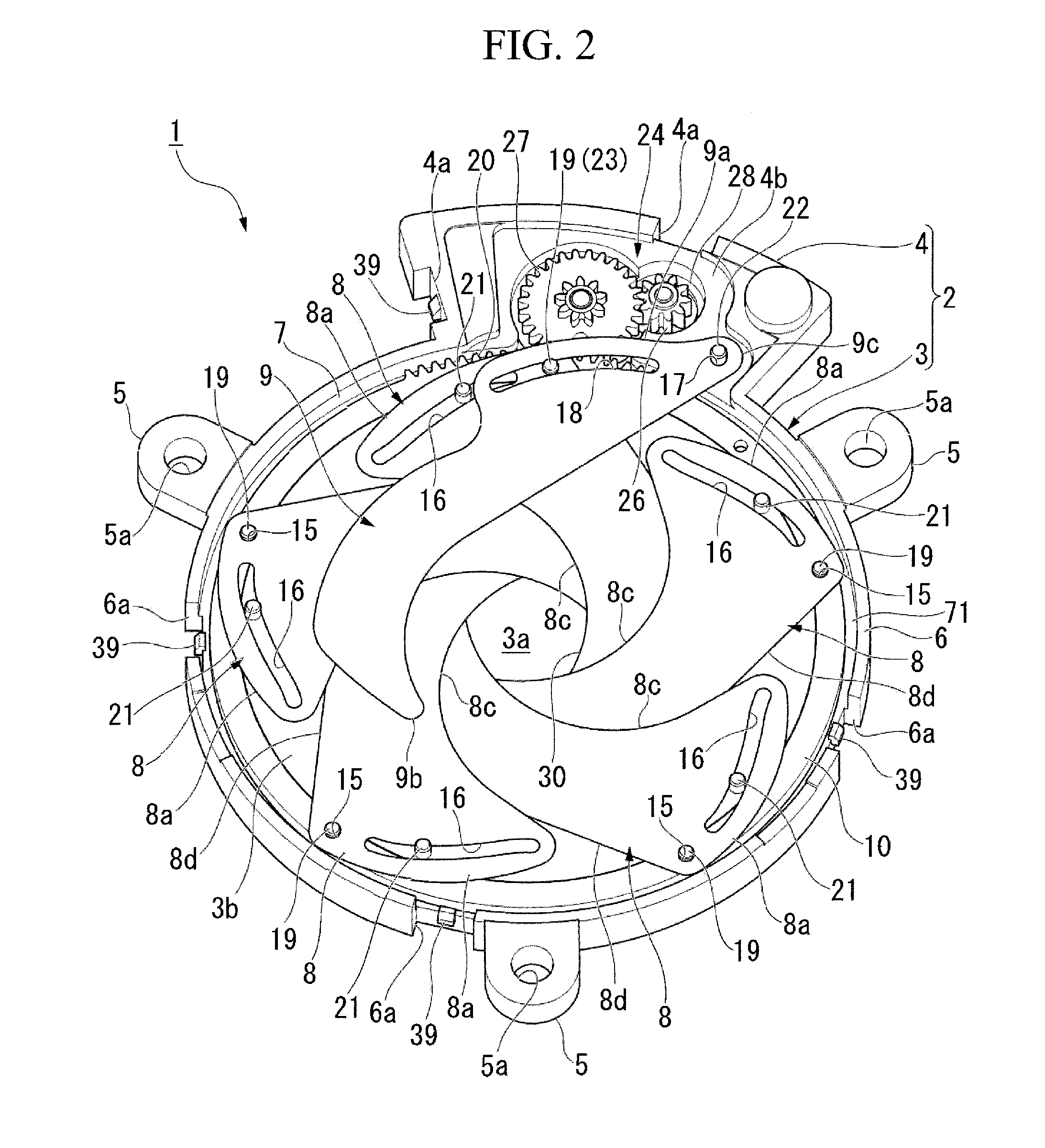
[0044]FIG. 2 is a perspective view of the diaphragm device 1, while FIG. 3 is an exploded perspective view of the diaphragm device 1.

[0045]As is shown i...

second embodiment

[0088]Next, a second embodiment of this invention will be described based on FIG. 8. Note that aspects that are the same as in the first embodiment are allocated the same descriptive symbols and any description thereof is omitted.

[0089]FIG. 8 is a plan view showing a state in which only one diaphragm blade 8 and a drive ring 210 are housed in the blade housing portion 7 of the base plate 2 of a diaphragm device 201 according to the second embodiment, and this view corresponds to the above-described FIG. 5.

[0090]As is shown in FIG. 8, the second embodiment differs from the above-described first embodiment in that the shape of the drive ring 210 of the second embodiment is different from the shape of the drive ring 10 of the first embodiment. Moreover, the second embodiment also differs from the first embodiment in that, in the first embodiment, drive force from the motor 25 is transmitted to the drive ring 10 via the rotor pinion 26 and the intermediate gear 27, however, in the secon...


PUM


Abstract

A diaphragm device of the present invention includes: a base plate having an aperture portion; a first blade being placed on a plane of the base plate and supported by the base plate to be able to open and close the aperture portion; a second blade being placed on the same plane of the base plate as the first blade, and supported by the base plate to be able to open and close the aperture portion; and a drive ring being formed so as to surround the perimeter of the aperture portion, the driving ring being configured to drive the first blade and the second blade to open and close, wherein the first blade and the second blade perform mutually different actions based on an operation of the drive ring.

Description

RELATED APPLICATIONS[0001]This application claims priority under 35 U.S.C. §119 to Japanese Patent Application No. 2014-233965 filed on Nov. 18, 2014, the entire content of which is hereby incorporated by reference.BACKGROUND OF THE INVENTION[0002]1. Field of the Invention[0003]The present invention relates to a diaphragm device and an optical instrument.[0004]2. Description of the Related Art[0005]For example, in optical instruments such as digital cameras and still cameras there is provided a diaphragm device that adjusts the amount of light that passes through the lens. A diaphragm device is provided with a base plate having an aperture portion, a plurality of diaphragm blades that are supported such that they are able to open and close the aperture portion, and a drive ring that causes the plurality of aperture blades to open or close. The plurality of diaphragm blades are arranged such that they are interlaced with each other along a circumferential direction. Accordingly, a st...

Claims


Application Information

Patent Timeline
Patent Type & Authority Applications(United States)
IPC IPC(8): G03B9/06
CPCG03B9/06
Inventor NAKANO, TAKASHIWORAPONG, PENJAN
Owner SEIKO HLDG KK TRADING AS SEIKO HLDG CORP
Why Eureka
Try Eureka