
Optimization of gimbal control loops using dynamically measured friction

Inactive Publication Date: 2016-05-19
BAE SYST INFORMATION & ELECTRONICS SYST INTERGRATION INC
View PDF3 Cites 7 Cited by
  • Summary
  • Abstract
  • Description
  • Claims
  • Application Information

AI Technical Summary

Benefits of technology

The patent describes a method for controlling the movement of a gimbal axis in an infrared countermeasure system (IRCM). The method involves using a high torque motor and a servo amplifier to drive the gimbal axis to its peak current and generating a maximum acceleration profile for the gimbal axis. The friction of the gimbal axis during acceleration is measured and used to calculate an optimum deceleration rate for the gimbal axis. A dynamic rate limit is selected based on the polarity of the angle change and the direction of predicted angular rate at the end of a slew event. The dynamic rate limit is then provided to the gimbal axis to control its movement. This method allows for smoother and more accurate movement of the gimbal axis in the IRCM system.

Problems solved by technology

Unfortunately, friction is considered to be a difficult parameter to calibrate since it depends on a number of different condition such as: (1) temperature of the lubricant; (2) axial and radial preloads that depend on temperature coefficients of expansion in steady-state; (3) axial and radial preloads that vary with temperature gradients in transient conditions; (4) wear; and (5) lubricant aging.
Thus, factory calibration on sensors must be followed to keep updated all conditions of a gimbal system, which is expensive and only partially effective.

Method used


Image

  • Optimization of gimbal control loops using dynamically measured friction
  • Optimization of gimbal control loops using dynamically measured friction
  • Optimization of gimbal control loops using dynamically measured friction

Examples


Embodiment Construction

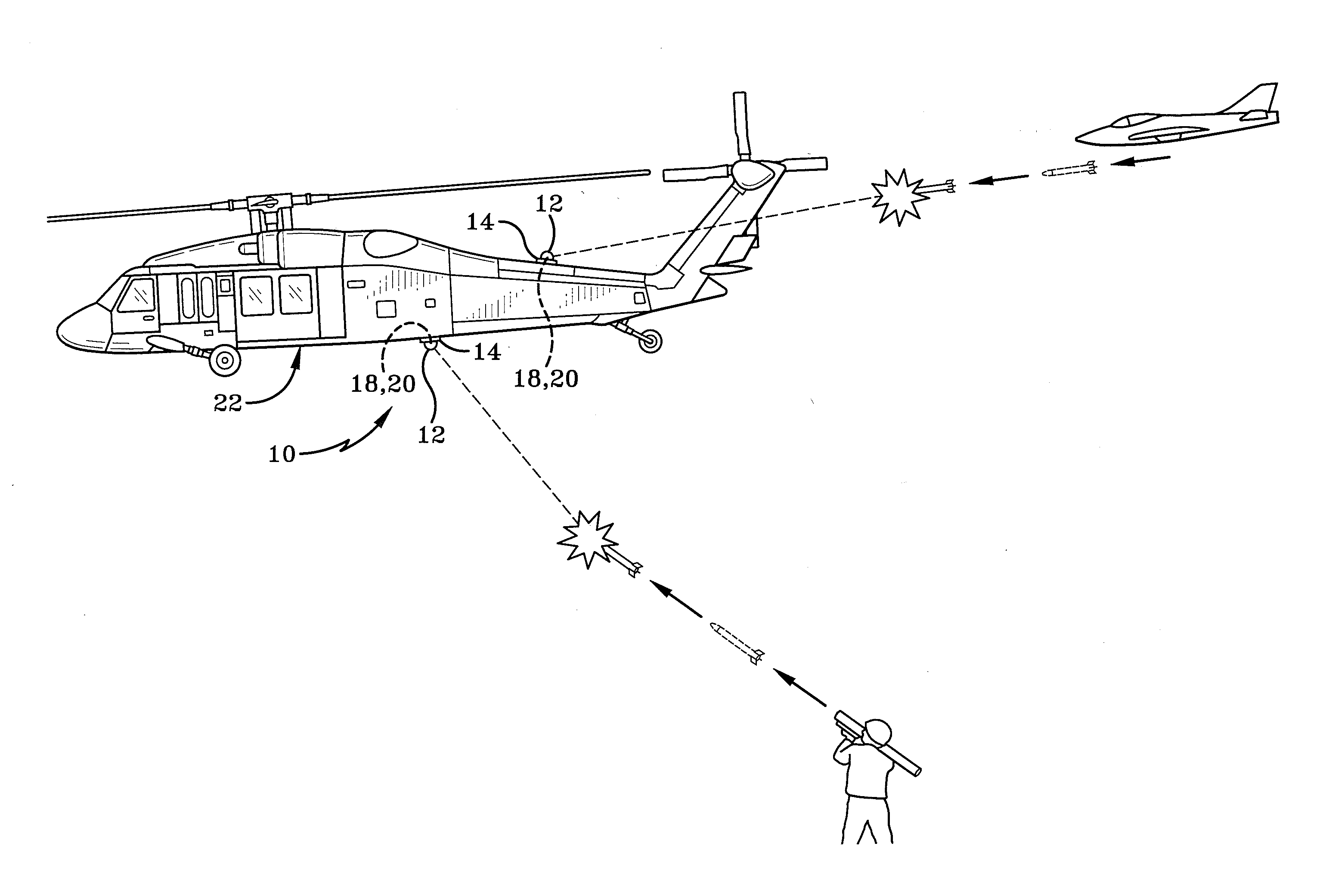
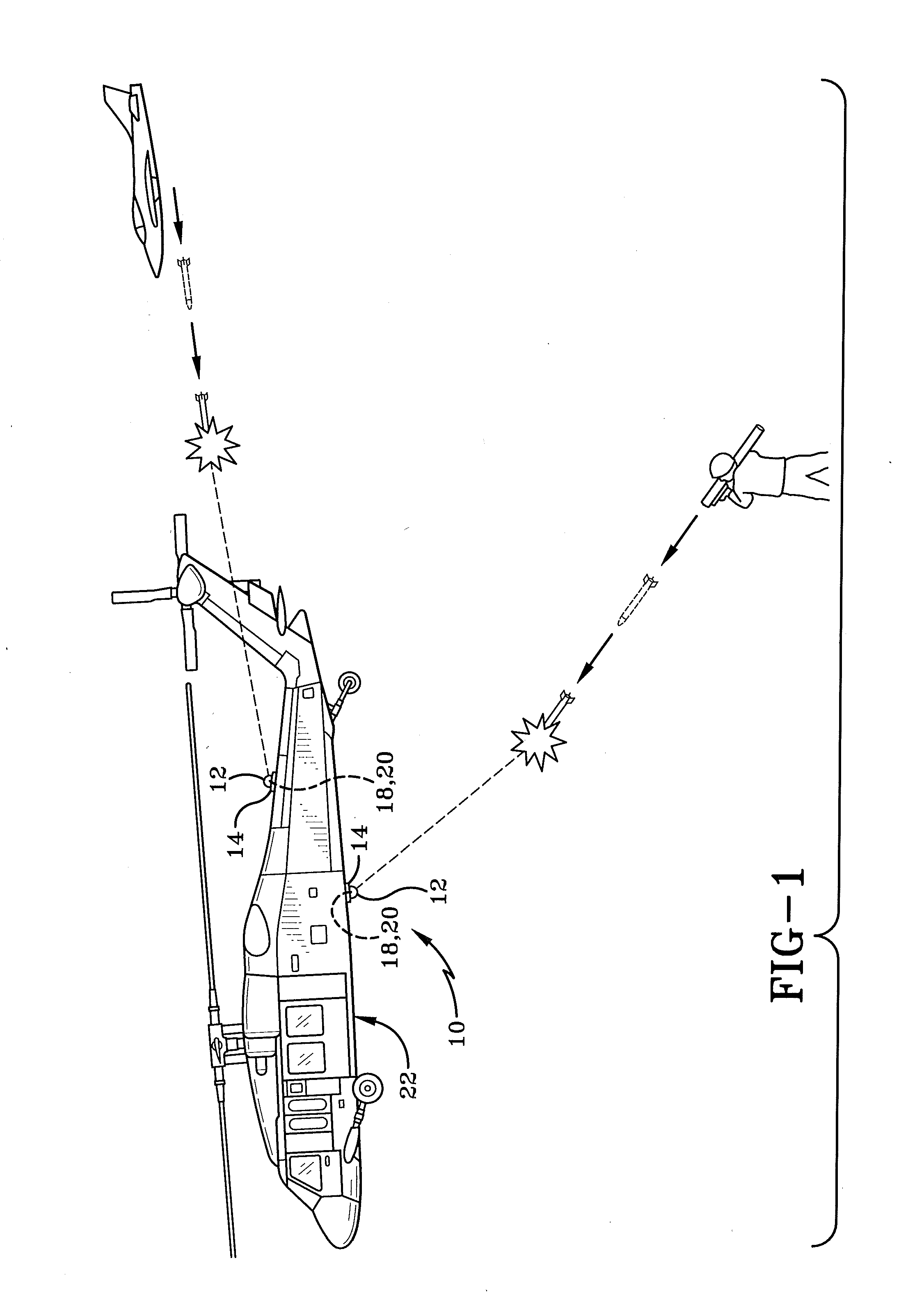
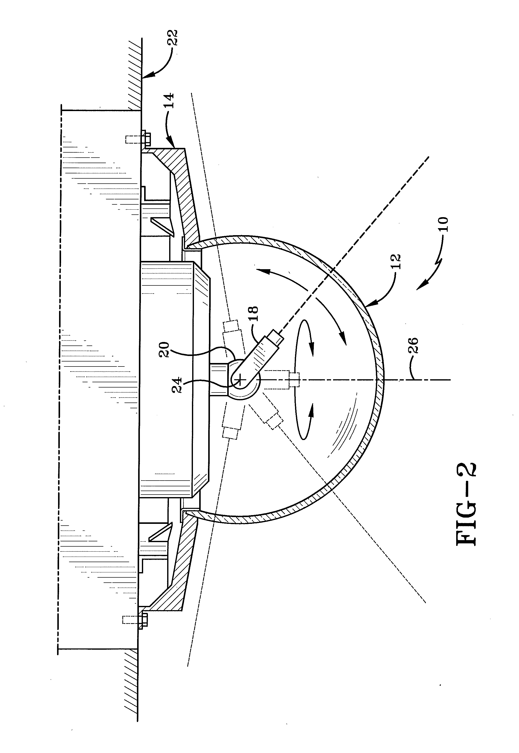
[0017]The current application is related to a countermeasure system which is mounted on an aircraft. As depicted in FIG. 1, the countermeasure system is mounted on aircraft 22. Aircraft 22 is depicted as a helicopter but may be any other form of flying device as one having ordinary skill in the art would understand. By way of a brief introduction, infrared countermeasure system 10 is a device designed to protect aircraft from infrared homing (“heat seeking”) missiles by confusing the missiles' infrared guidance system so that they will miss their target (Electronic countermeasure). Referring to FIG. 2, the countermeasure system 10 comprises infrared (IR) transparent dome 12, a dome base 14, an electro-optical (EO) system 18, and a gimbal system 20. Electro-optical system 18 is further mounted on gimbal system 20. Gimbal system 20 enables electro-optical system 18 to move in vertical and horizontal directions freely so that electro-optical system 18 mounted on gimbal system 20 can po...


PUM


Abstract

A method to slew a gimbal axis in an infrared countermeasures system (IRCM) comprising the steps of driving the motors up to the peak currents allowed by the servo amplifiers, moving the profile generator from firmware to software for design flexibility, forcing high torque by manipulating the angle waveform sent to hardware, measuring friction during acceleration of each slew, providing a dynamic rate limit for receding or advancing angle goals is presented in this application.

Description

CROSS-REFERENCE TO RELATED APPLICATIONS[0001]This application claims the benefit of U.S. Provisional Patent Application Ser. No. 62 / 080,691, filed Nov. 17, 2014, the entire specification of which is incorporated herein by reference.BACKGROUND[0002]1. Technical Field[0003]Generally the application relates to electronic countermeasures and more particularly to infrared countermeasures systems. More particularly, the application relates to a gimbal system which comprises azimuth and elevation axes utilized in infrared countermeasure systems. Specifically, this application is directed to a method to measure gimbal friction dynamically at the beginning of a slew event so that a deceleration profile can be generated to position gimbal axes at the target angle.[0004]2. Background Information[0005]Optimizing a weapon slew to assure that it moves quickly is becoming ever more important. Thus, to slew a gimbal axis as quickly as possible to match a target angle and angular rate requires knowl...

Claims


Application Information

Patent Timeline
IPC IPC(8): G05B19/19
CPCG05B19/19F41H11/02G05B2219/37373G05B2219/37497G05B2219/37543G05B2219/42284
Inventor CASELEY, CLIFFORD D.DIONNE, AUSTIN J.MESSIER, PAUL F.
Owner BAE SYST INFORMATION & ELECTRONICS SYST INTERGRATION INC
Features
  • Generate Ideas
  • Intellectual Property
  • Life Sciences
  • Materials
  • Tech Scout
  • Unparalleled Data Quality
  • Higher Quality Content
  • 60% Fewer Hallucinations
Learn More