
Electric vehicle

a technology of electric vehicles and electric motors, applied in the direction of battery/fuel cell control arrangement, propulsion by capacitors, instruments, etc., can solve the problem of long time required for pre-charge, and achieve the effect of shortening the time required

Active Publication Date: 2016-05-26
TOYOTA JIDOSHA KK
View PDF4 Cites 25 Cited by
  • Summary
  • Abstract
  • Description
  • Claims
  • Application Information

AI Technical Summary

Benefits of technology

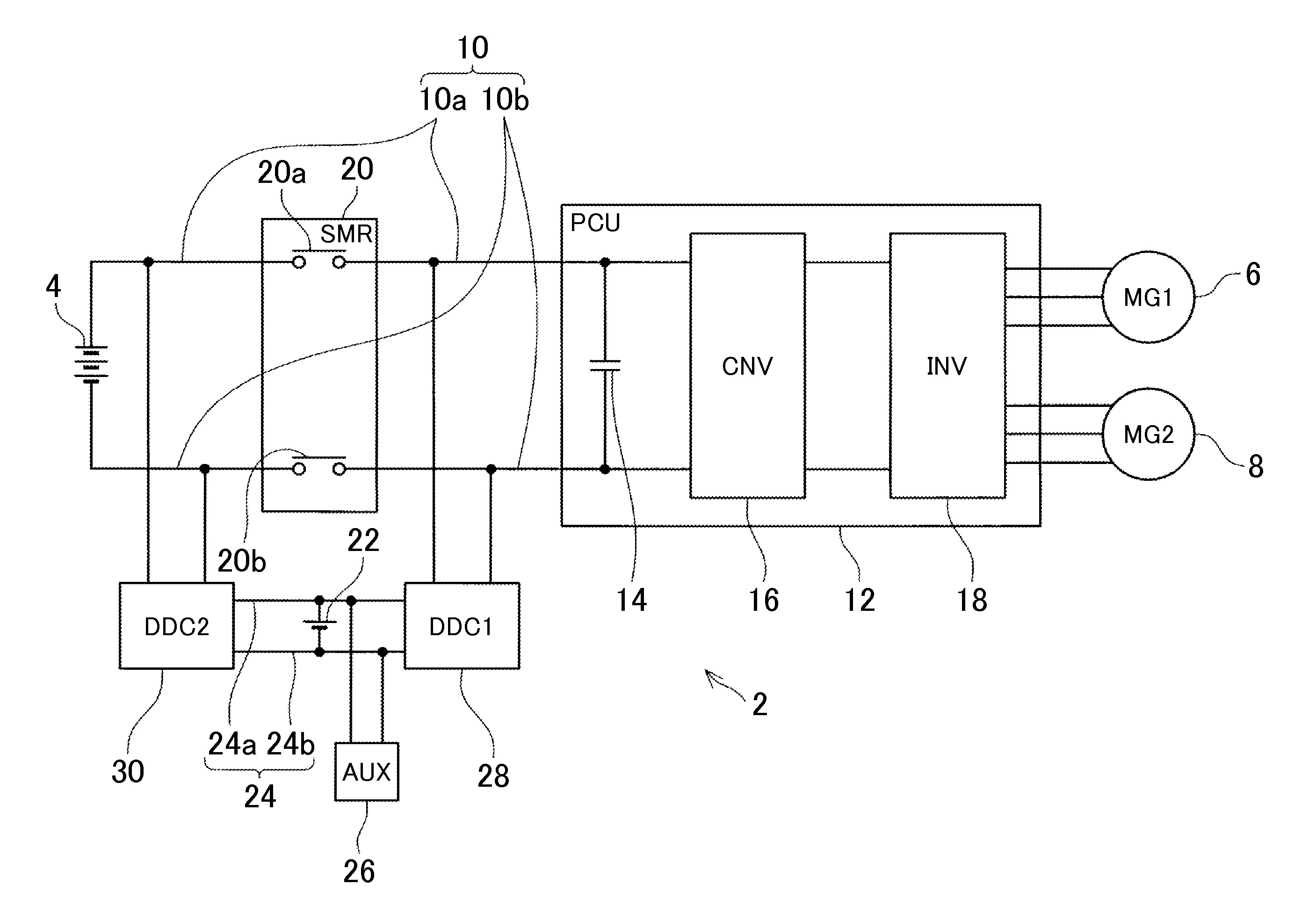
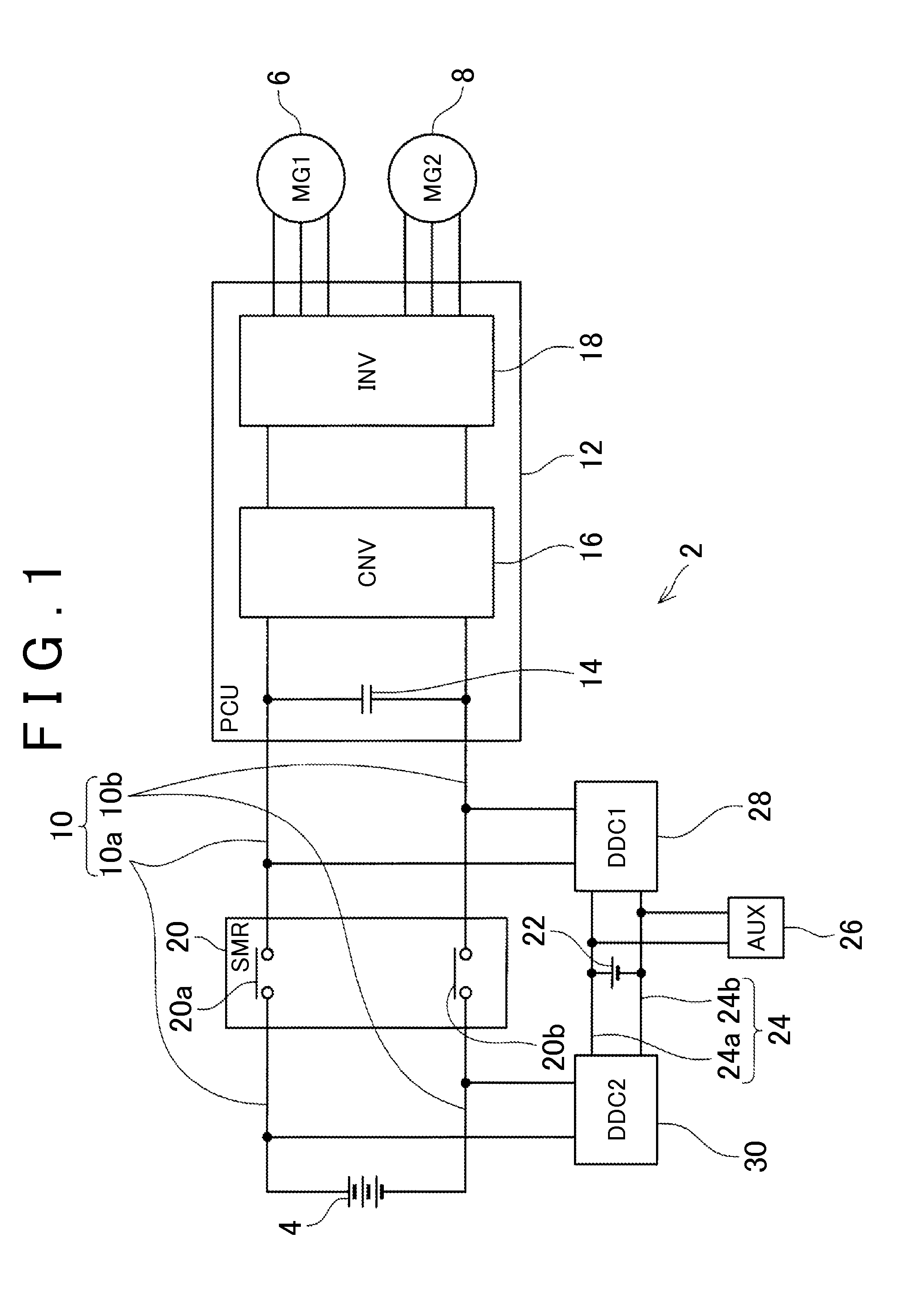
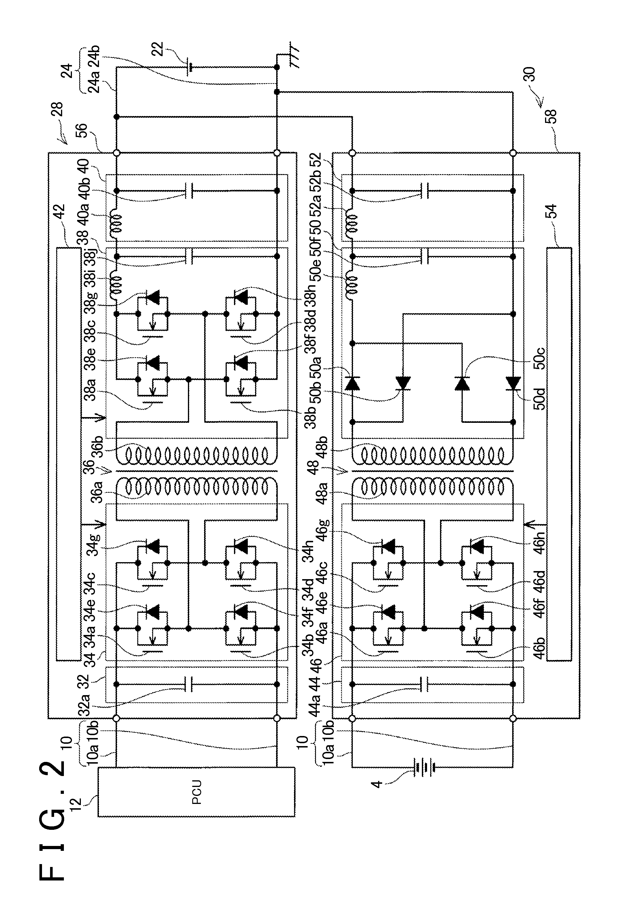
The patent text discusses a problem with the long time required for pre-charging a smoinking capacitor in an electric vehicle. The text describes a technique that uses two DC-DC converters to shorten the time required for pre-charging. The first converter performs a boost operation to supply power to the smouring capacitor from a sub-battery, while the second converter performs a buck operation to supply power from the main battery to the capacitor. This configuration reduces the time needed for pre-charging and minimizes the sudden changes in output current that can cause high inrush current.

Problems solved by technology

In the case of performing the pre-charge of the smoothing capacitor by supplying the electric power from the sub battery, since the sub battery cannot supply a high electric power, the pre-charge requires a long time.

Method used


Image

  • Electric vehicle
  • Electric vehicle
  • Electric vehicle

Examples


Embodiment Construction

[0020]In some embodiments, in the electric vehicle, the first DC-DC converter is a bidirectional DC-DC converter further capable of performing a buck operation to buck electric power from the main electric power supply wire and to supply the electric power to the sub electric power supply wire. Such a configuration makes it possible to charge the sub battery by supplying the electric power from the electric power control unit to the sub battery, regardless of the conduction / non-conduction of the switch. Further, such a configuration makes it possible to charge the sub battery using both of the first DC-DC converter and the second DC-DC converter, during the conduction of the switch, allowing for the shortening of the time required for the charge of the sub battery.

[0021]In some embodiments, in the electric vehicle, the second DC-DC converter is a unidirectional DC-DC converter capable of performing only the buck operation. Such a configuration makes it possible to reduce the manufac...


PUM


Abstract

An electric vehicle disclosed in the specification includes a main battery, a main electric power supply wire connected with the main battery, an electric power control unit including a smoothing capacitor that smooths a voltage of the main electric power supply wire, a switch that switches the main electric power supply wire between conduction and non-conduction, a sub battery having a lower voltage than the main battery, a sub electric power supply wire connected with the sub battery, a first DC-DC converter that can perform a boost operation from the sub electric power supply wire to the main electric power supply wire on the electric power control unit side relative to the switch, and a second DC-DC converter that can perform a buck operation from the main electric power supply wire on the main battery side to the sub electric power supply wire.

Description

INCORPORATION BY REFERENCE[0001]The disclosure of Japanese Patent Application No. 2014-238705 filed on Nov. 26, 2014 including the specification, drawings and abstract is incorporated herein by reference in its entirety.BACKGROUND OF THE INVENTION[0002]1. Field of the Invention[0003]The technology disclosed in the specification relates to an electric vehicle having a motor for running The “electric vehicle” in the specification includes both an electric vehicle having only a motor for running without having an engine and a hybrid vehicle having the motor for running as well as the engine.[0004]2. Description of Related Art[0005]Japanese Patent Application Publication No. 2007-318849 discloses an electric vehicle including a main battery, a main electric power supply wire connected with the main battery, an electric power control unit including a smoothing capacitor that a smooths the voltage of the main electric power supply wire, a switch that is between the main battery and the el...

Claims


Application Information

Patent Timeline
Patent Type & Authority Applications(United States)
IPC IPC(8): B60L11/18H02M3/335H02J7/02
CPCH02M3/33507B60L11/18B60L50/40B60L3/00B60L2210/14B60L2210/12H02M3/33584B60L1/00B60L15/007B60L2210/10B60L2240/547B60L2270/147B60L2240/527B60L58/20Y02T10/70Y02T10/64Y02T10/72
Inventor NOZAWA, TAKASHI
Owner TOYOTA JIDOSHA KK
Learn More