Automatic driving system for automatically driven vehicle

Active Publication Date: 2016-05-26
DENSO CORP
View PDF33 Cites 100 Cited by
  • Summary
  • Abstract
  • Description
  • Claims
  • Application Information

AI Technical Summary

Benefits of technology

[0011]The above automatic driving system is configured to, if determining that each of the lanes in the parking lot is unidirectional, allow automatic driving of the automatically driven vehicle. With this configuration, when each of the lanes in the parking lot is unidirectional, the likelihood that the automatically driven vehicle and another vehicle f

Problems solved by technology

Without traffic rules, a vehicle could travel freely, but it would be difficult to avoid the other vehicles in the environment without more accurately monitoring the other vehicles in the environment and more accurately driving t

Method used


Image

  • Automatic driving system for automatically driven vehicle
  • Automatic driving system for automatically driven vehicle
  • Automatic driving system for automatically driven vehicle

Examples


first embodiment

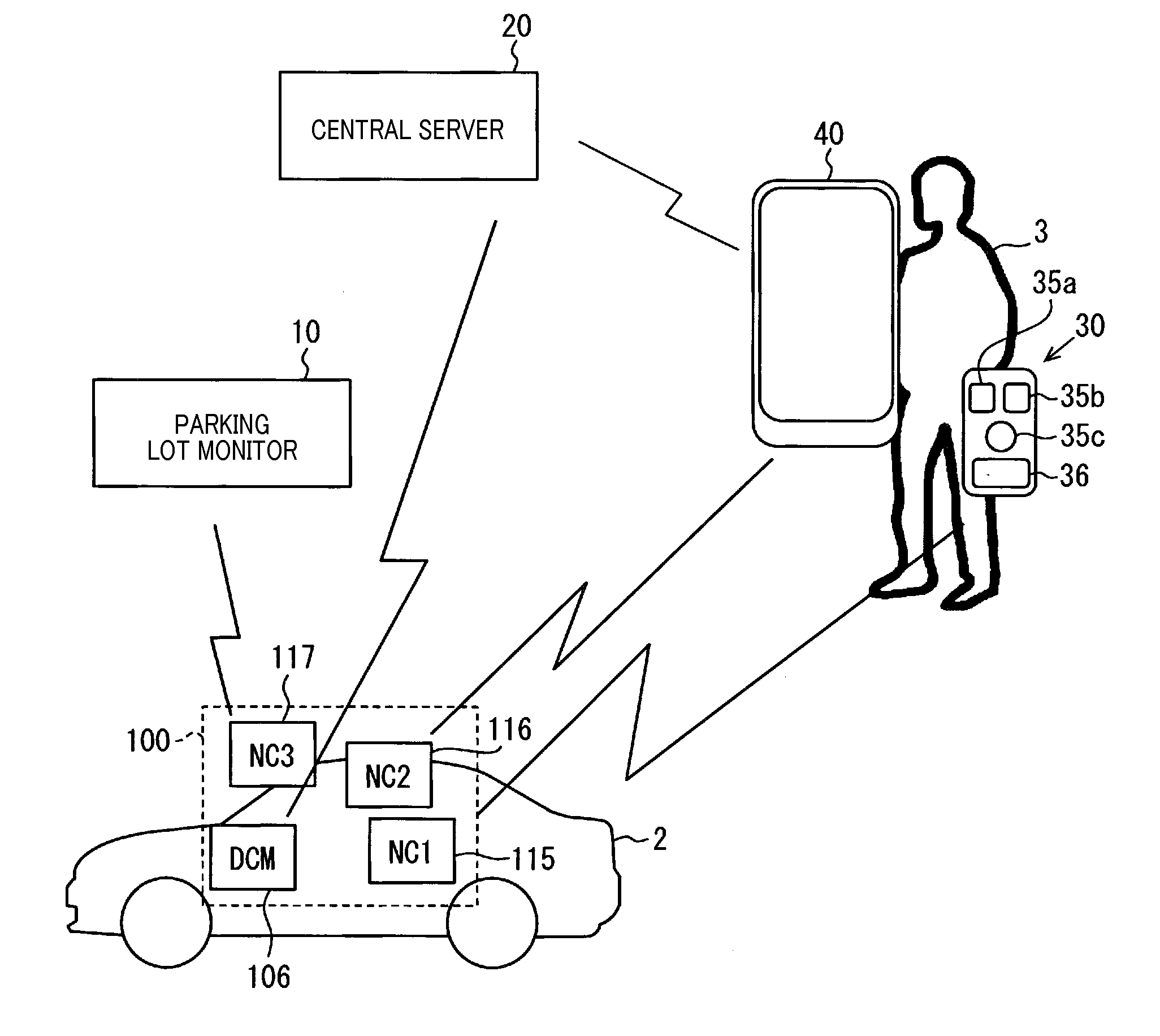
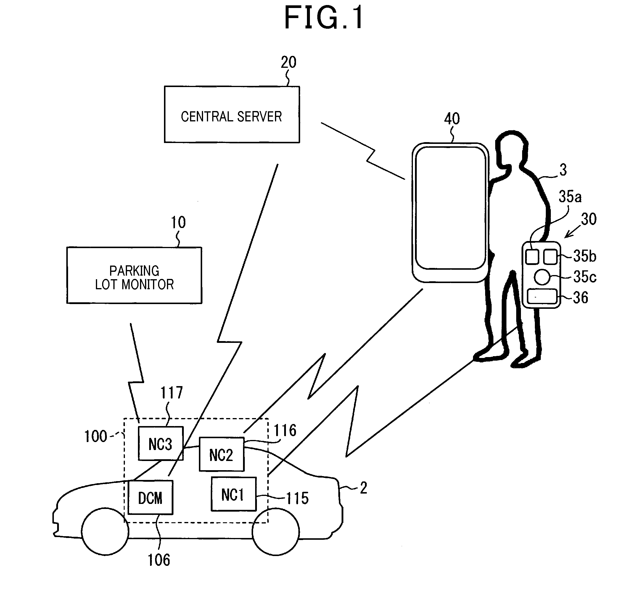
[0033]An automatic driving system 1 for an automatically driven vehicle in accordance with a first embodiment of the present invention will now be explained with reference to FIG. 1. The automatic driving system 1 includes, as shown in FIG. 1, a parking lot monitor 10, a central server 20, an electronic key 30 (as a mobile device), a smartphone 40 (as a mobile device), and a vehicle-mounted system 100. The smartphone 40 also serves as a mobile communication device.

[0034]The vehicle-mounted system 100 is mounted in the automatically driven vehicle 2. The electronic key 30 and the smartphone 40 are carried by a user 3 of the automatically driven vehicle 2. Automatic driving of the vehicle 2 is enabled by the vehicle-mounted system 100. Further, manned driving of the vehicle 2 is enabled as well. As shown in FIG. 1, the vehicle-mounted system 100 includes a data communication module (DCM) 106, a first near field communication unit (NC1) 115, a second near field communication unit (NC2)...

second embodiment

[0137]A second embodiment of the present invention will now be explained. In the present and subsequent embodiments, elements having the same functions as in the first embodiment are assigned the same numbers, except where specified otherwise, and will not be described again for brevity.

[0138]In the present embodiment, the controller 38 of the electronic key 30 performs the process shown in FIG. 12 as an alternative to the process of FIG. 8. In step S41, it is determined whether or not the automatic driving switch 35c has been pressed. If in step S41 it is determined that the automatic driving switch 35c has not been pressed yet, then the process of FIG. 12 ends. If in step S41 it is determined that the automatic driving switch 35c has been pressed, then the process of FIG. 12 proceeds to step S42.

[0139]In step S42, it is determined whether or not the electronic key 30 is linked to the smartphone 40. That is, for example, it is determined whether or not authentication between the el...

third embodiment

[0148]A third embodiment will now be explained with reference to FIG. 13. In the present embodiment, after automatic driving is started, a process of FIG. 13, as an alternative to the process of FIG. 11, is performed. In FIG. 13, steps S51 to 56 are the same as steps S31 to S36 of FIG. 11. Steps S58, S59 are the same as steps S38, S39 of FIG. 11. That is, the process of FIG. 13 is different from the process of FIG. 11 only in step S57.

[0149]In step S57, a driving condition signal (as a surroundings condition signal) including the current location of the automatically driven vehicle 2 detected as in step S37 and the latest forward and rearward images is transmitted to the smartphone 40. The forward image is an image captured by the front-facing camera 102, and the rearward image is an image captured by the rear-facing camera 103.

[0150]To transmit the driving condition signal, it is necessary that the vehicle-mounted system 100 and the smartphone 40 are linked to each other. To start ...


PUM


Abstract

An automatic driving system for an automatically driven vehicle. In the system, a travel direction acquirer is configured to acquire travel direction information that is information indicative of whether or not each of lanes in a parking lot is unidirectional. In addition, in the system, an allowance determination unit is configured to, if determining, based on the travel direction information acquired by the travel direction acquirer, that each of the lanes in the parking lot is unidirectional, allow automatic driving of the automatically driven vehicle.

Description

CROSS-REFERENCE TO RELATED APPLICATION[0001]This application is based on and claims the benefit of priority from earlier Japanese Patent Application No. 2014-238979 filed Nov. 26, 2014, the description of which is incorporated herein by reference.BACKGROUND[0002]1. Technical Field[0003]The present invention relates to an automatic driving system for an automatically driven vehicle and particularly to a technique for enabling automatic driving of the automatically driven vehicle in a parking lot.[0004]2. Related Art[0005]Some techniques for automatically driving a vehicle have become increasingly practical. For example, in a known technique as disclosed in Japanese Patent Application Laid-Open Publication No. 2014-102750, a fixed station has a map stored therein of a controlled area where a vehicle is allowed to be driven automatically. The fixed station sequentially receives travel data from an automatic driving unit mounted in the vehicle. Based on the received travel data and the ...

Claims


Application Information

Patent Timeline
IPC IPC(8): B60W30/06G05D1/00
CPCB60W30/06G05D1/0088B60W2710/30B60W2550/22B60W2900/00G05D1/0061G05D2201/0213G08G1/04G08G1/056G08G1/144G08G1/146G08G1/207B60W2555/60B60W2540/045B60W60/0059B60W2555/20B60W40/02B60W50/082B60W2420/403B60W2420/52
Inventor OHSHIMA, HIROAKI
Owner DENSO CORP
Why Eureka
Try Eureka