Rotary Conveyor with Change of Pitch for Transferring Containers

Active Publication Date: 2016-05-26
MARTI SALA JAIME +1
View PDF7 Cites 1 Cited by
  • Summary
  • Abstract
  • Description
  • Claims
  • Application Information

AI Technical Summary

Benefits of technology

The invention allows for easy replacement of a closed-loop cam without changing or modifying the suction chamber. The suction chamber is designed with low-friction sliding bearings and a rotary coupling to a low pressure source, which allows air flows at a high flow rate and slow speed to keep containers in place. The invention also uses a fan powered by a motor to achieve the desired air flow. These technical effects improve efficiency and flexibility in the industrial container handling process.

Problems solved by technology

First, the fact that the upper wall of the suction chamber is in contact with a lower surface of the rotary platform can generate considerable friction resulting in unacceptable component wear and / or heating.
On the other hand, the fact of using the slots formed in the rotary platform both for the passage of the corresponding cam followers and for the passage of air at their intersections with the suction slot requires high precision in the paths of the closed-loop cam, the slots formed in the rotary platform and the suction slot for obtaining an acceptable air flow rate in any position without considerable losses, which imposes certain limitations in the design of such paths.

Method used


Image

  • Rotary Conveyor with Change of Pitch for Transferring Containers
  • Rotary Conveyor with Change of Pitch for Transferring Containers
  • Rotary Conveyor with Change of Pitch for Transferring Containers

Examples


Embodiment Construction

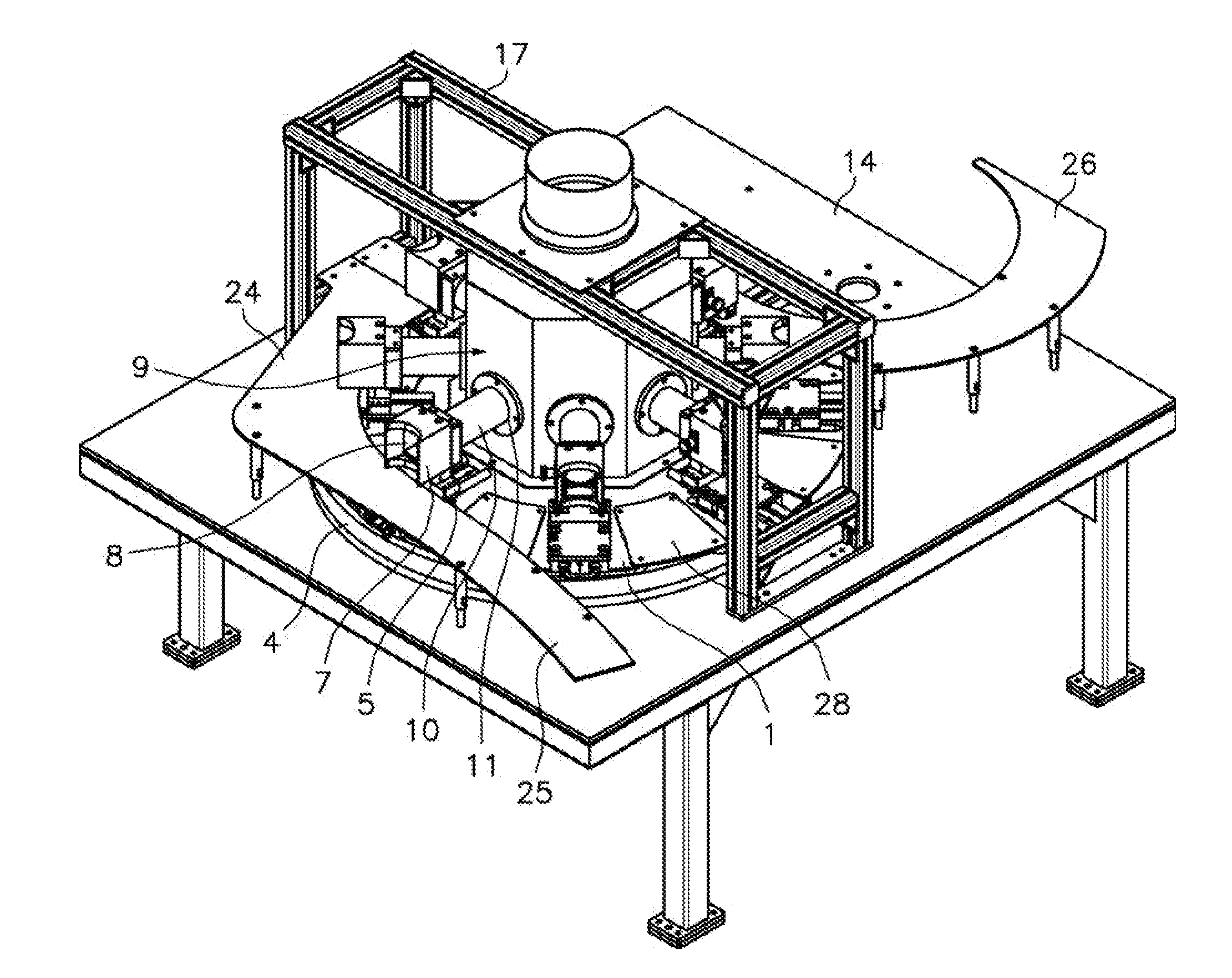
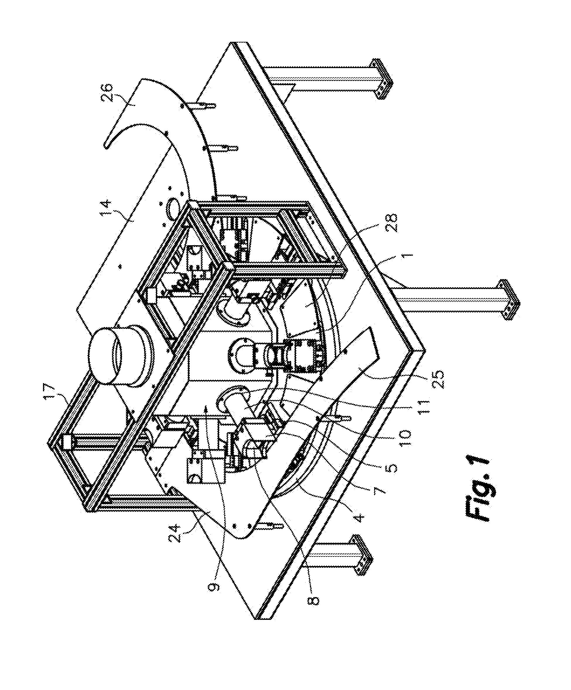
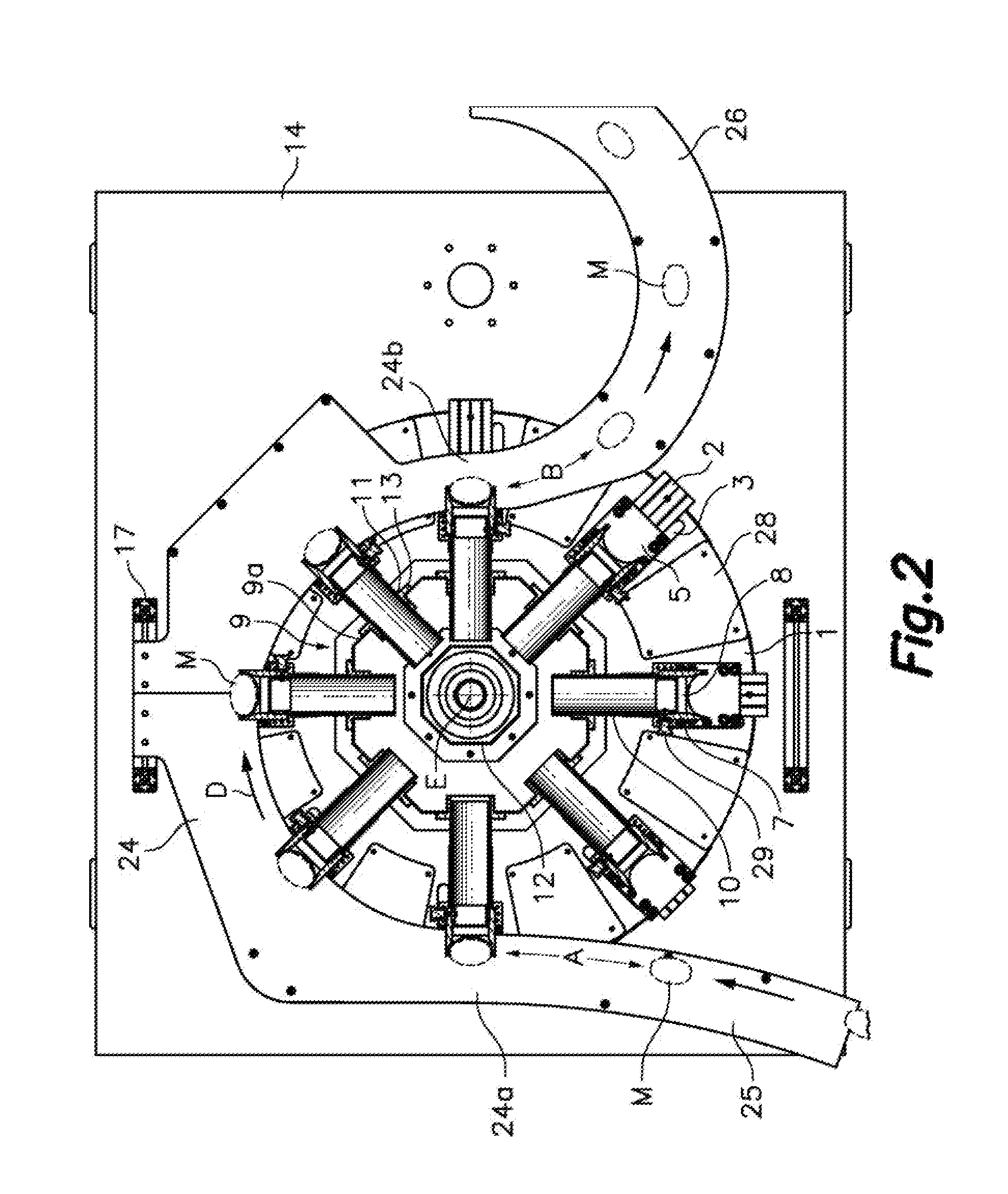
[0024]FIGS. 1, 2 and 3 show a rotary conveyor with change of pitch for transferring containers according to an embodiment of the present invention comprising a frame 14 including a horizontal surface on which a closed-loop cam 4 is fixed in a stationary position. The frame 14 furthermore supports a drive shaft 16 by means of ball bearings 18 (FIG. 3), such that the drive shaft 16 can rotate about a vertical rotation axis E. The drive shaft 16 has fixed thereto a driven pulley 19 (FIG. 3) which is part of a mechanical transmission connecting the driven pulley 19 fixed to the drive shaft 16 to a driving pulley (not shown) operatively connected to be driven by a motor (not shown) so that the motor rotates the drive shaft 16.

[0025]An upper end of the drive shaft 16 is fixed to a rotary platform 1 located above the closed-loop cam 4, such that the rotary platform 1 rotates together with drive shaft 16 about the rotation axis E in the direction indicated by arrow D in FIG. 2.

[0026]As show...


PUM


Abstract

The rotary conveyor with change of pitch for transferring containers comprises a plurality of slides (5) radially guided on a rotary platform (1) rotating about a rotation axis (E) and on which a suction chamber (9) having a plurality of side openings (11) is fixed. A stationary closed-loop cam (4) not centered with respect to the rotation axis (E) is located below the rotary platform (1). Each slide (5) has fixed thereto a retention element (7) provided with a suction port (8) suitable for retaining a container and a suction conduit (10) having an outer open end connected to the suction port (8), an inner open end located inside the suction chamber (9), and an intermediate portion slidingly inserted in a corresponding one of the side openings (11) of the suction chamber (9).

Description

CROSS-REFERENCE TO RELATED APPLICATIONS[0001]This application claims priority from European Application No. EP14380036 filed on Nov. 24, 2014.FIELD OF THE INVENTION[0002]The present invention relates to a rotary conveyor with change of pitch useful for transferring containers from an infeed conveyor to an outfeed conveyor, where the containers are conveyed by the infeed conveyor at a first pitch, i.e., separated from one another by a first distance, and delivered to the outfeed conveyor at a second pitch, i.e., separated from one another by a second distance, different from the first pitch.BACKGROUND OF THE INVENTION[0003]Document EP 2226277 B1 discloses a rotary conveyor for transferring containers comprising a rotor driven by a motor to rotate around rotation axis. The rotor has a perimetric wall having a plurality of suction openings distributed over its periphery in correspondence with retention elements configured to engage the containers. In a region inside the perimetric wall...

Claims


Application Information

Patent Timeline
IPC IPC(8): B65G47/91B65G47/22
CPCB65G47/22B65G47/914B65G29/00B65G47/848B65G2201/0244B65G47/915
Inventor MARTI SALA, JAIMEMARTI MERCADE, ALEX
Owner MARTI SALA JAIME
Why Eureka
Try Eureka